
All work indicated below are my own and individual contribution.
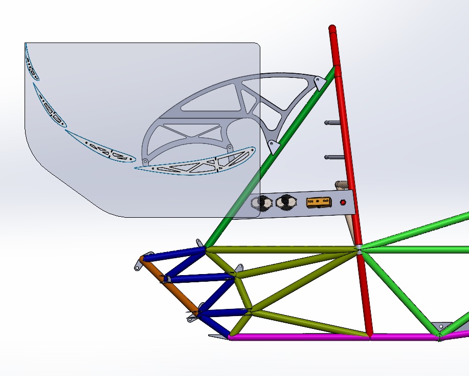
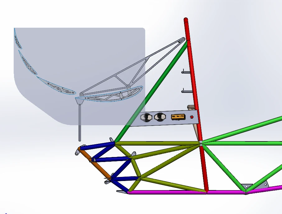
On the left, the old mounting assembly, and the new one on the right
Analysis & Design
In order to reliably & effectively improve the design of the new mounting system, the applicable loading scenarios & effective load at each element needed to be derived.
Modelling the system
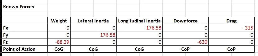
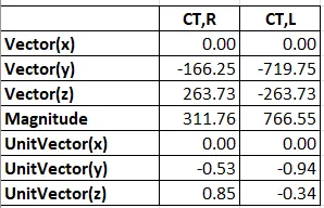
The known forces & unit vectors were denoted in a 3D system, and the model/system was not further simplified. This was to ensure that the forces acting on each component of the system were effective captured, especially in the case of cornering as the system of forces would not be symmetric.
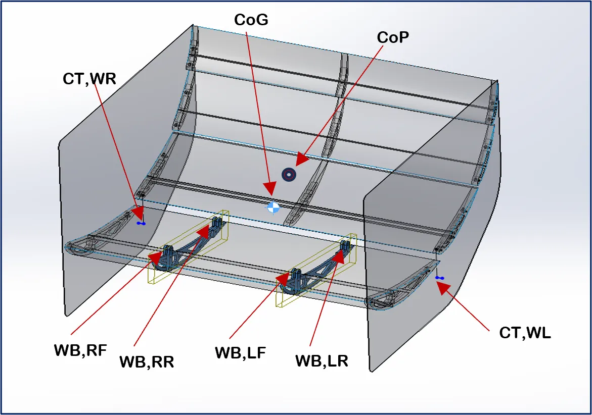
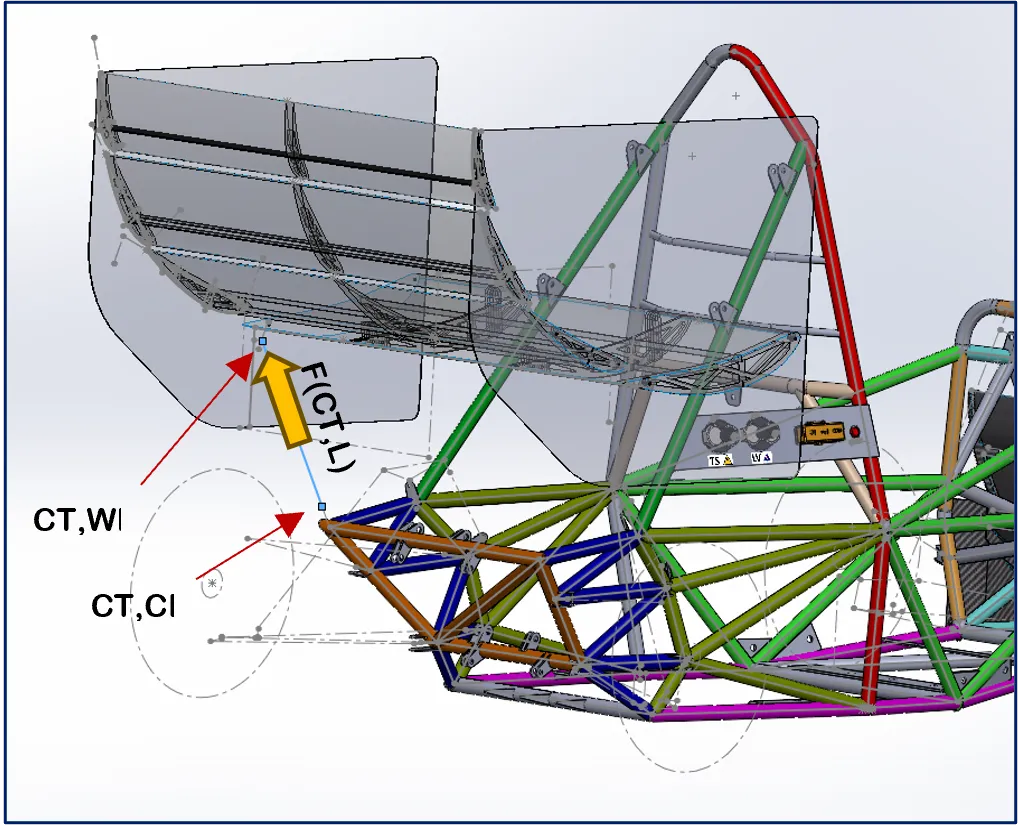
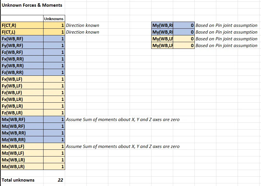
As shown below, the system contains more than 6 unknown component forces & moments (22 to be precise) which would make the system indeterminate if simply analyzed without taking to consideration the effect of deformation.
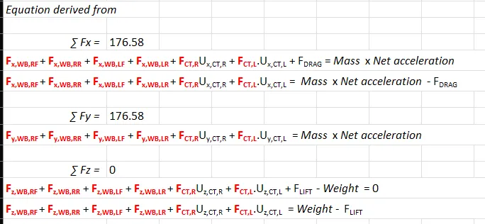
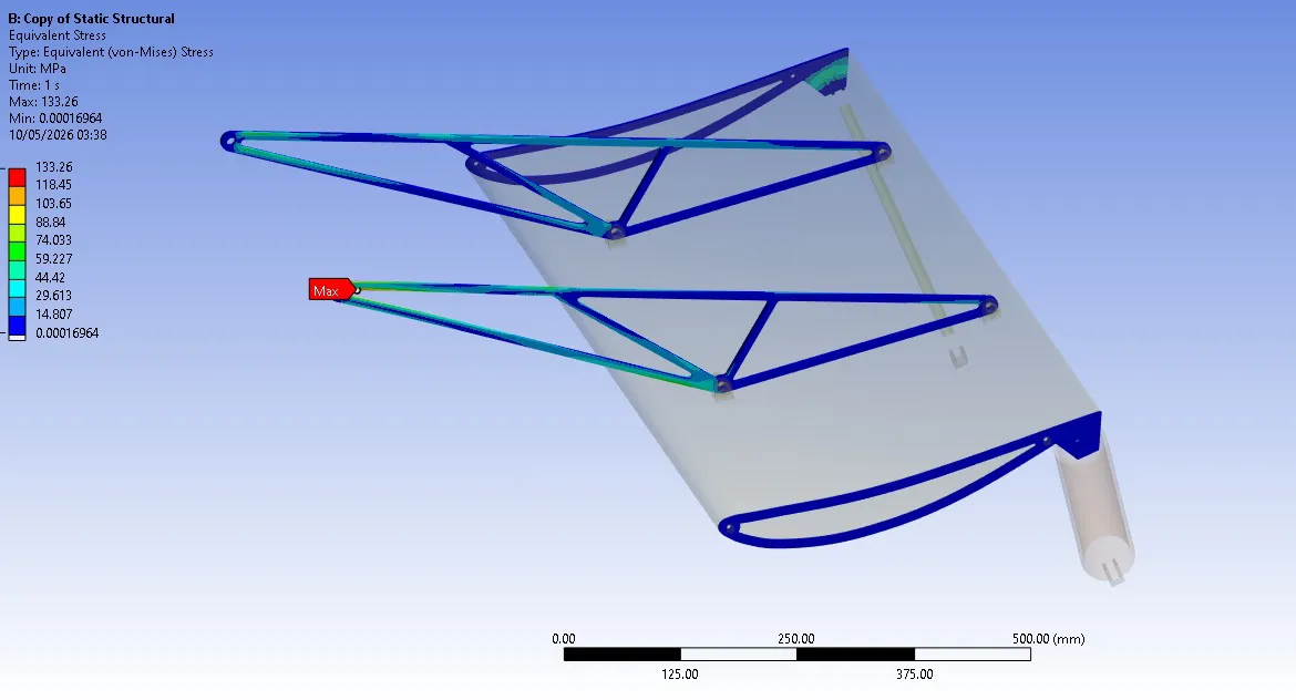
I decided instead to perform a multi-body analysis on ANSYS MECHANICAL by modelling contacts, joints & supports. The Carbon Fibre tubes below the wing & the main wing element were modelled as rigid bodies as it was assumed that deformation in these components will be minimal. Rodends were modelled as sphecial joitns at the bracket’s bolt connections as hinges.
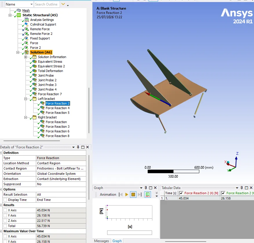
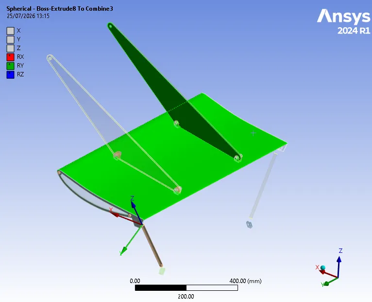
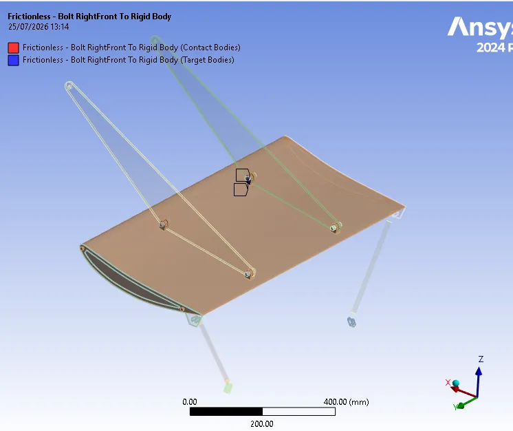
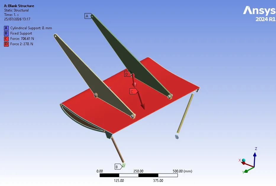
The system was constrained but computationally expensive, which required extensive mesh refinement.
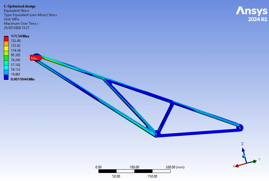
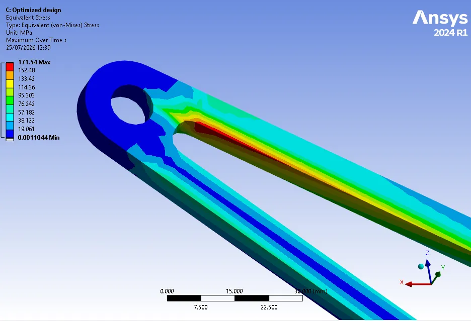
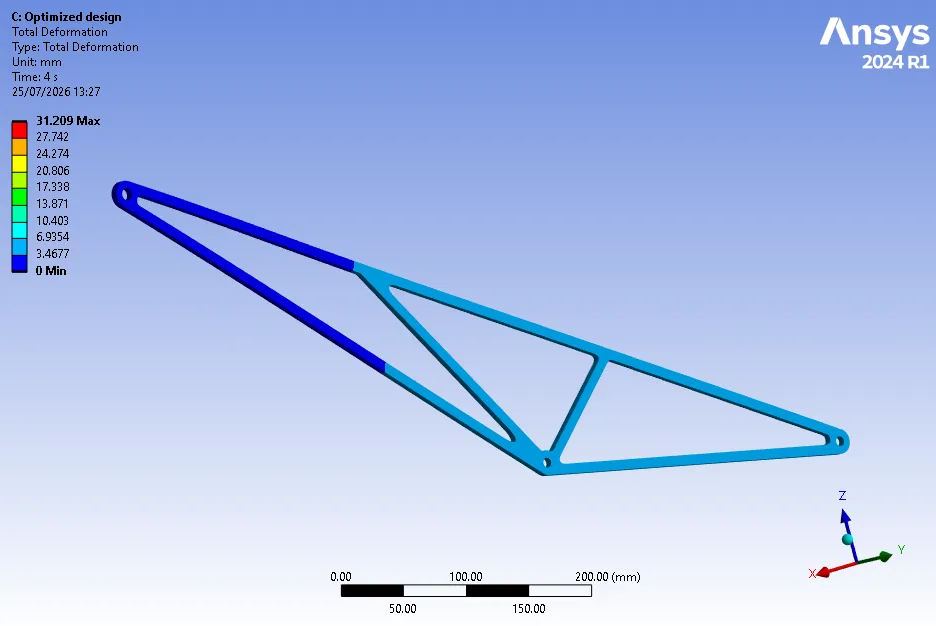
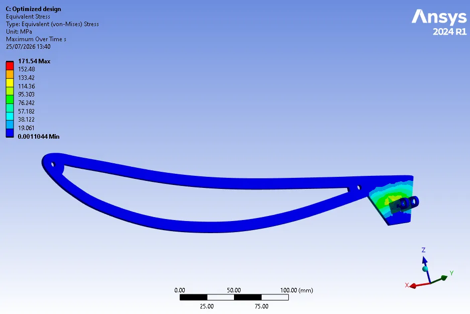
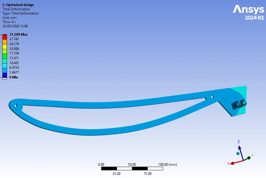
With the reaction forces obtained from the analysis above, component-wise design commenced.
Finalized Design
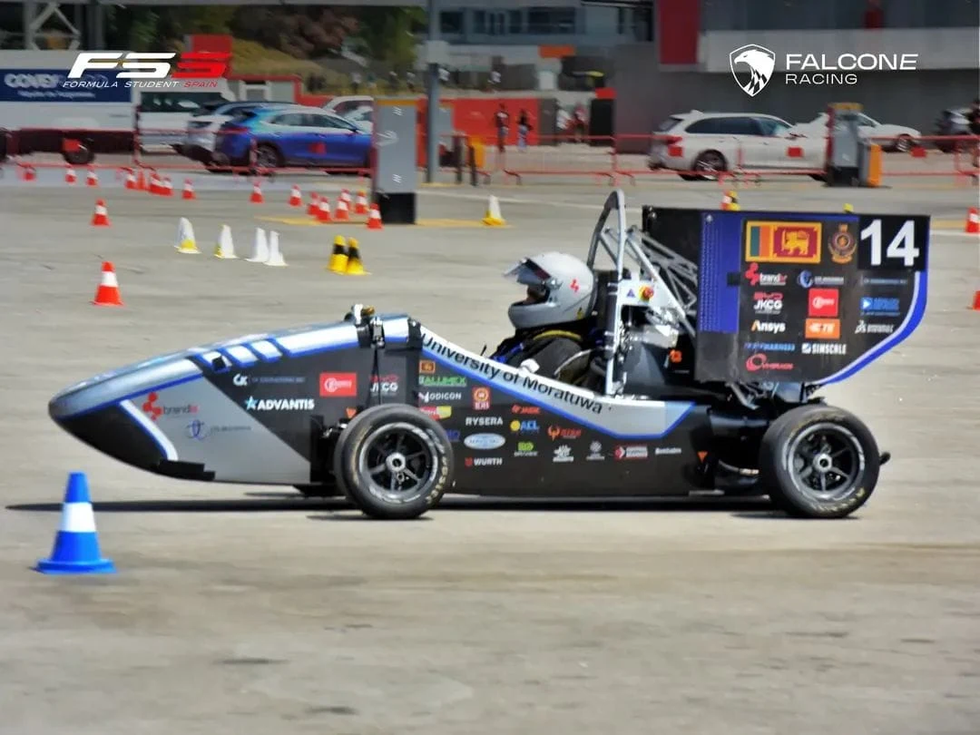
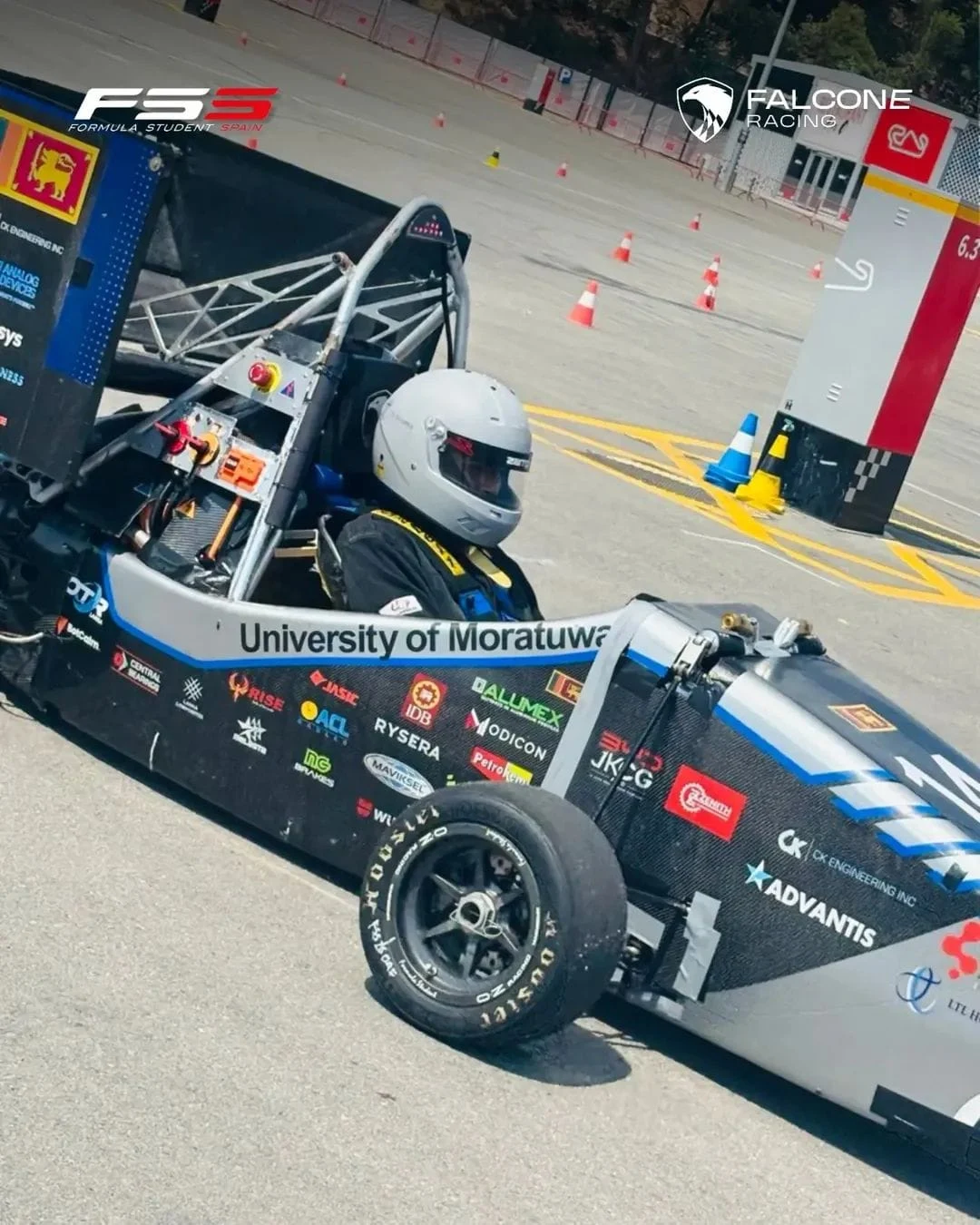
The new 720g design passed scrutineering at FS Spain 2026 & bore 12kg of added weight during inspection.
In the case of the two brackets, it is apparent that one bracket will be loaded more than the other in the instance of cornering.