All work indicated below are my own and individual contribution, & is my early work in the team
Problem Statement based on the pre-existing car
01
Extreme Steering Effort
The pre-exsiting front setup required a static steering torque exceeding 25Nm
02
Excessive rolling during cornering
Visual test data showed that the car was rolling more than 10 degrees during cornering.
03
Excessive Camber gain on the outside tyres
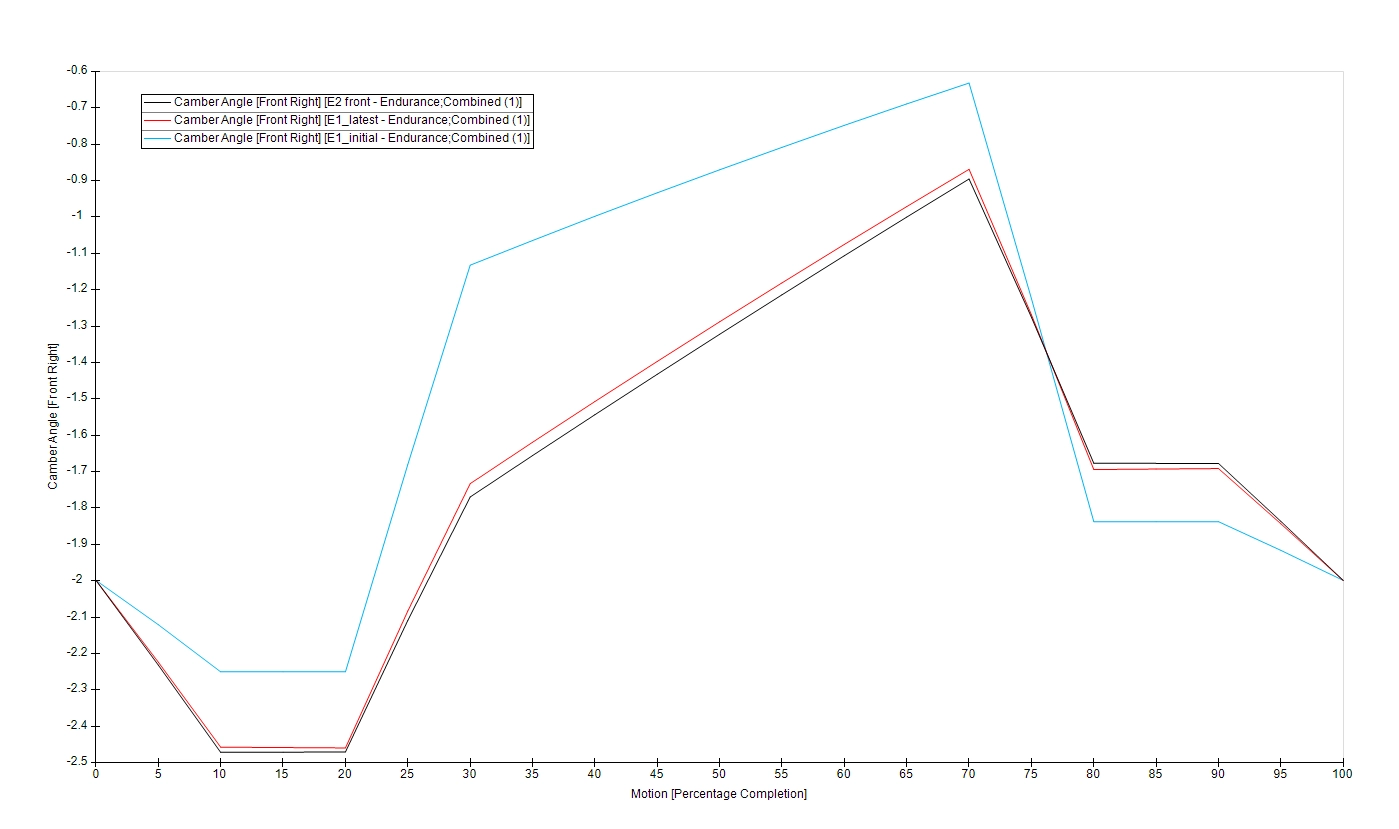
In line with the previous scenario, as well as due to the geometry of the suspension linkage, at a static camber of -2 degrees, the outside tyre would achieve a positive camber during roll.
Problem Study
As a junior member of the team, my task was to “fix” the above issues, while not making any changes to the steering rack & chassis. What entailed was a fortnight of rigorous studies and troubleshooting, referring to content from Milliken, Carrol Smith, Pat Clarke and Claude Roulle (of which I believe all are valuable content for a fundamental understanding of suspension systems)
Near Parallel Wishbones & large roll moment arm
This is a flexible section where you can share anything you want. It could be details or some information about your service one.
Usually, the driving “feel” derived from a symmetric scrub radius setup is a positive in general setups, but, for FSAE and FS cars, the short straights and rapid turning expected can be benefitted from a smaller scrub radius, which is considerable factor in determining steering torque.
Mechanical trail (MT) is a common factor in suspension and steering design, and is closely tied to the effects of the dynamic parameter-pneumatic trail(PT). The self-aligning torque achieved through the combination of MT and PT is ultimately the torque that should be exerted by the steering system at the Kingpin axis. In Formula Student, the short steering arms and tight cornering often makes the steering torque the priority.
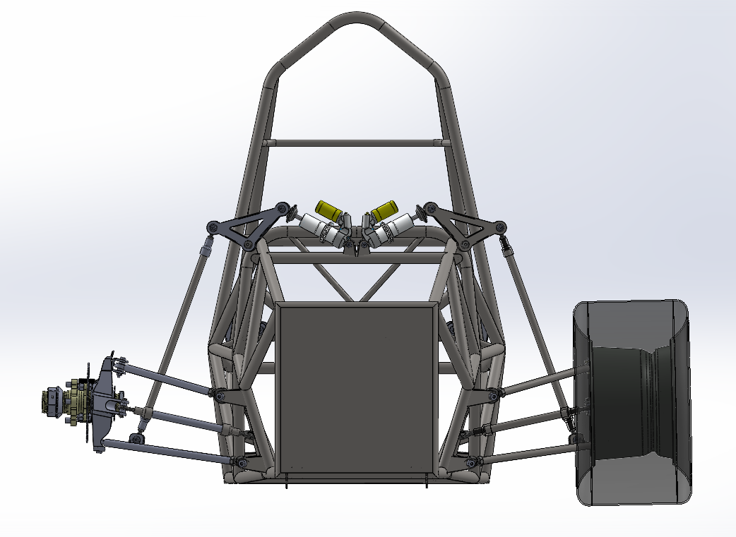
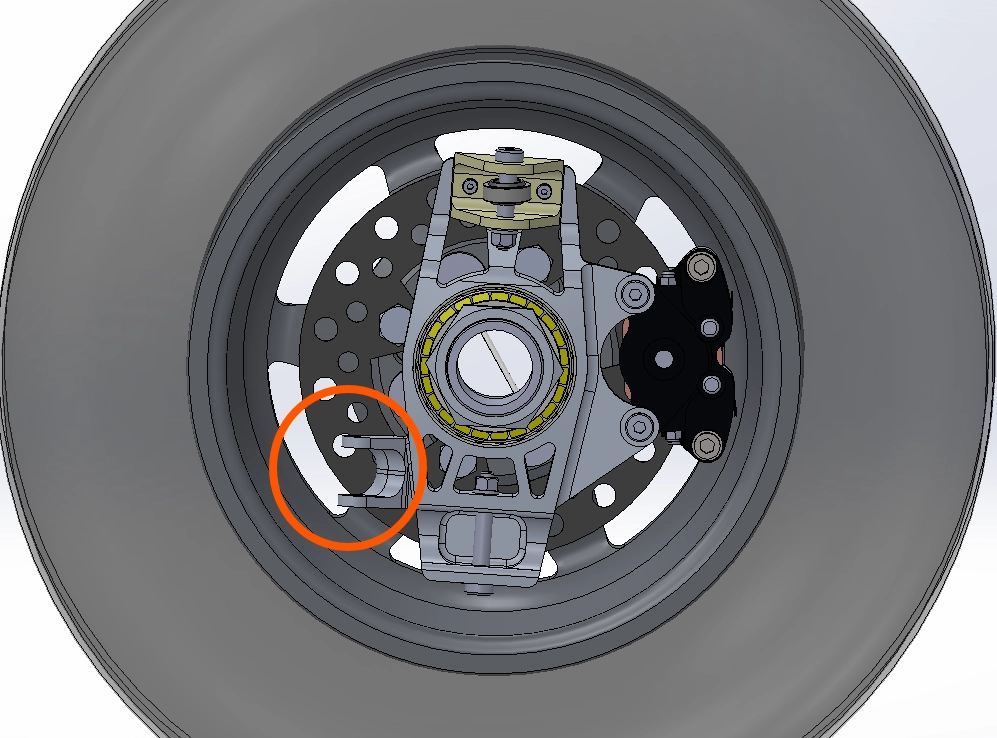
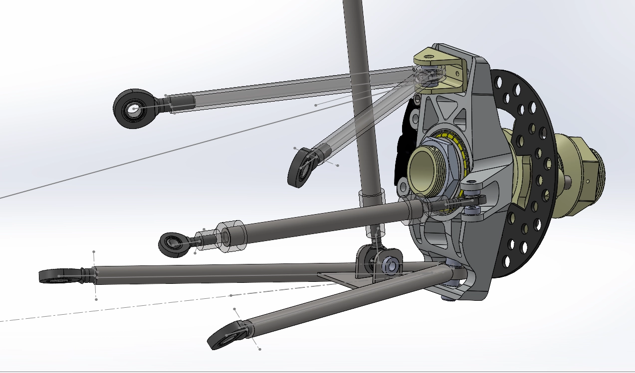
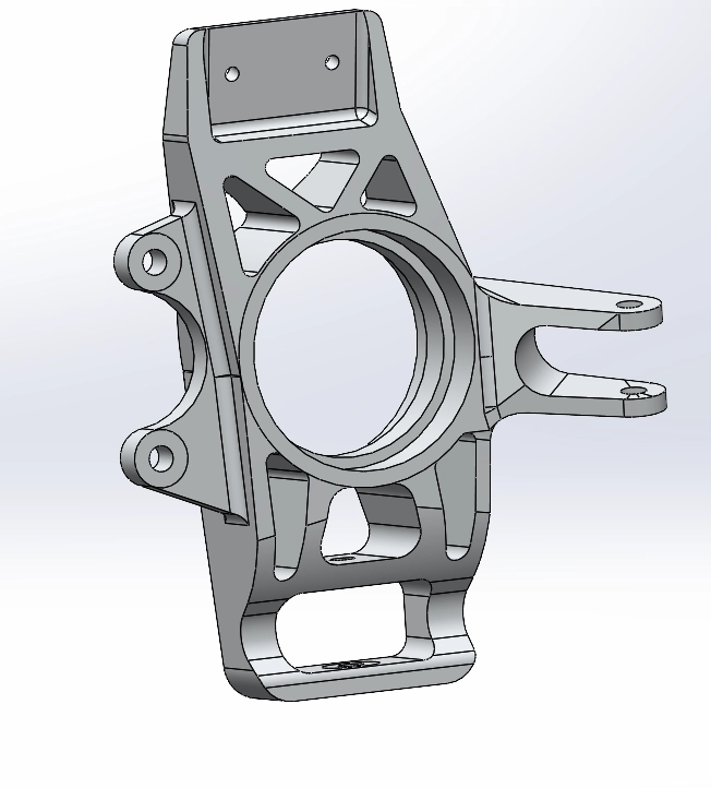
As evident in the image, the steering arm can be elongated to increase the moment arm about the Kingpin axis, in turn proportionally reducing the effort at the steering wheel.
The geometry of a suspension system is comprised of many pre-defined geometric constructions which allows designers to relate and discuss various aspects of different suspension systems.
As a newbie in the field, I took it upon myself to simulate and analyse the independent kinematic effects of each of these geometric properties on a predefined range of motion of the chassis and wheels (maximum extents of motion and combined effects of pitch and heave).1 This was done on OPTIMUMG’s OptimumKinematics software.
For this purpose, multiple suspension arrangements with changes in each geometric property. To simplify the content of this post, I’ve highlighted the analysis on the effects of varying Kingpin Inclinations and varying Caster angles2, and their effects on Camber gain.
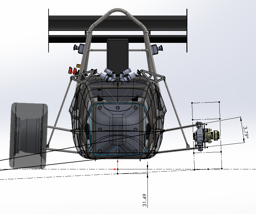
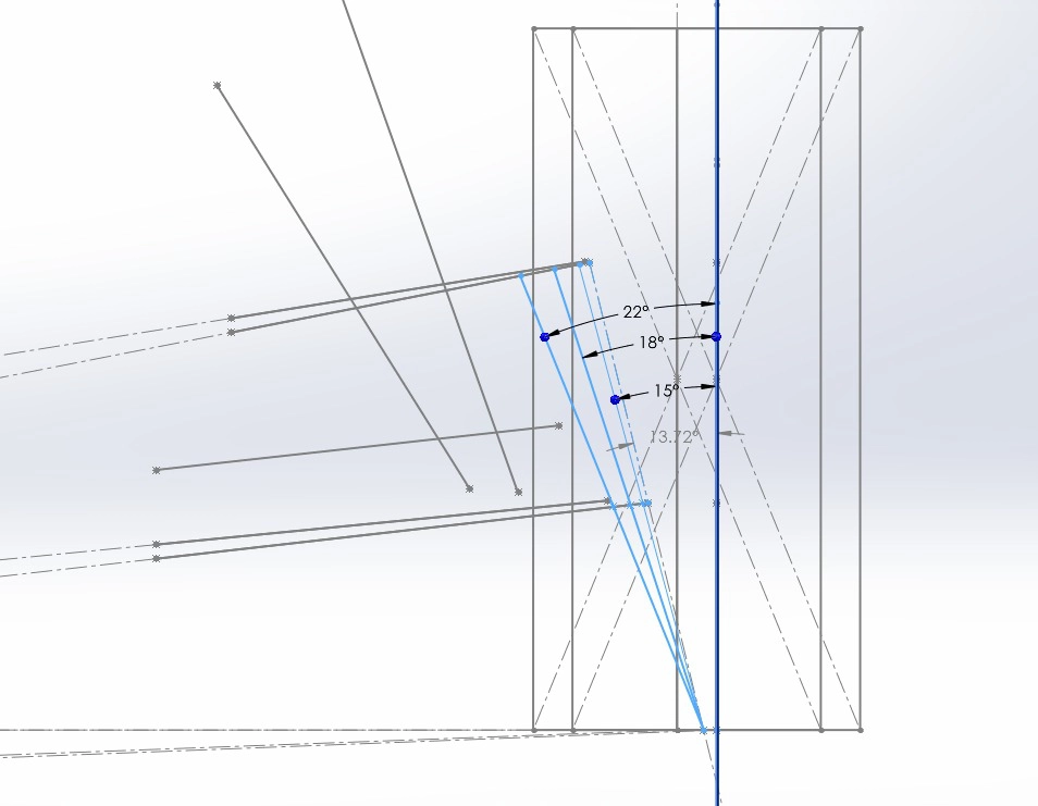
A few of the tested/simulated KPI variations
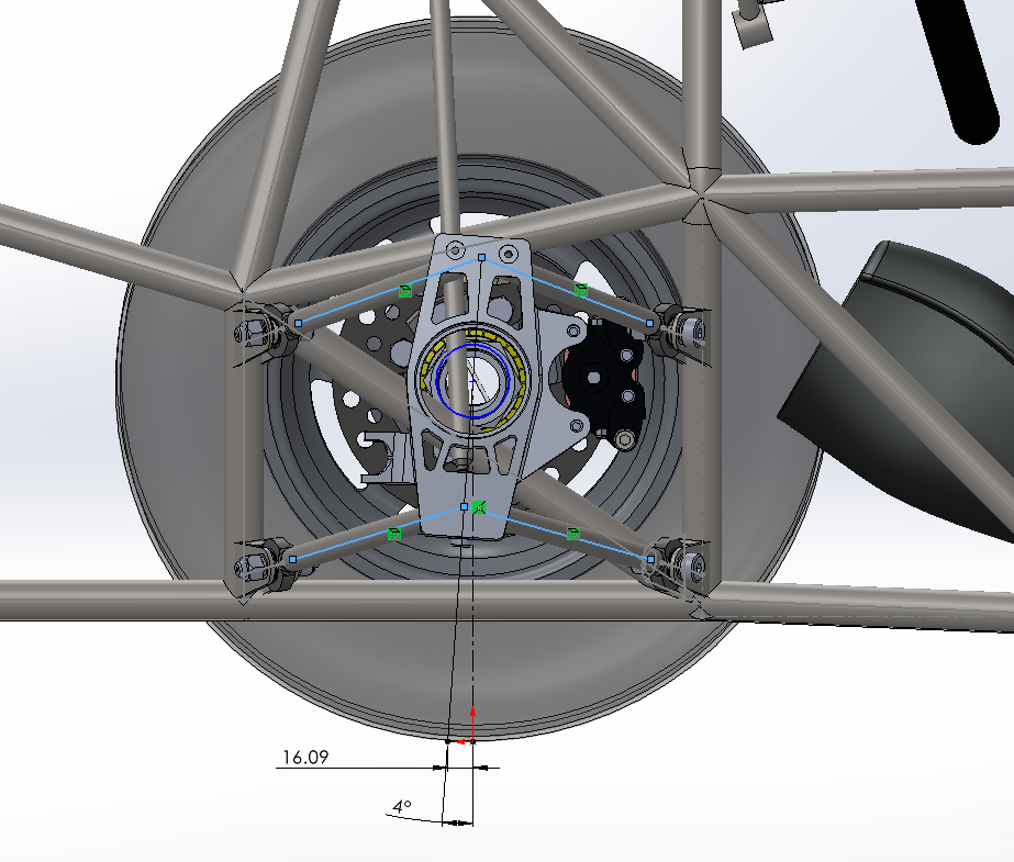
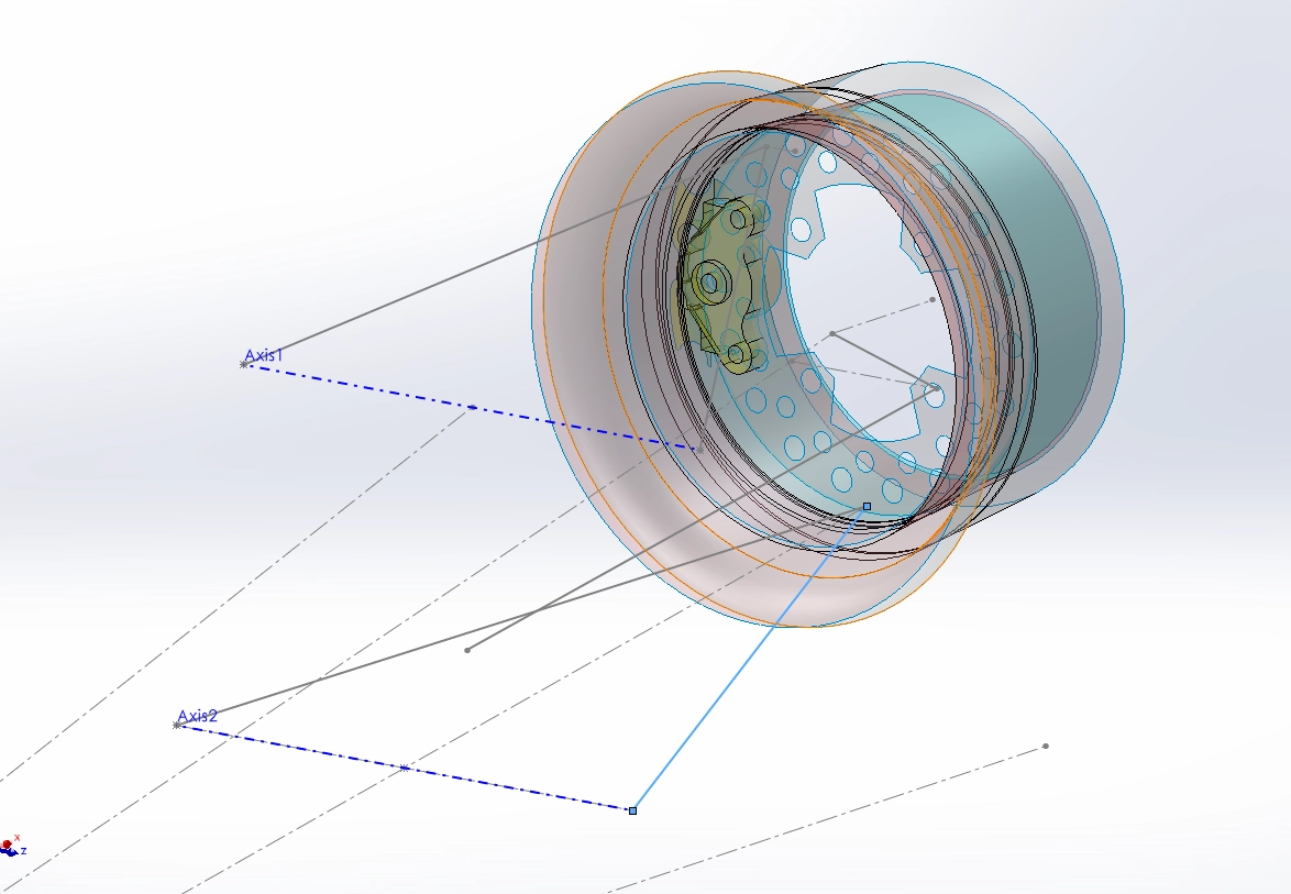
The practical feasibility of each point’s implementation was determined using offset surfaces in CAD. These surfaces defined a feasible and practical maximum limit at which each point(eg: tierod pickup point, Upright upper pickup point, etc.) could be positioned, relative to physical constraints such as the wheel and brake disc.
Multiple overset surfaces – defined to replicate the spatial constraints of each individual pickup point
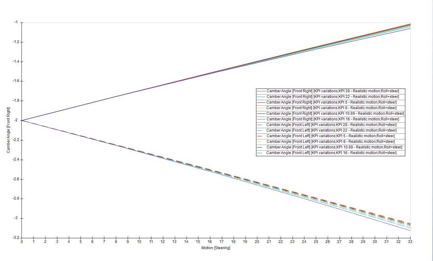
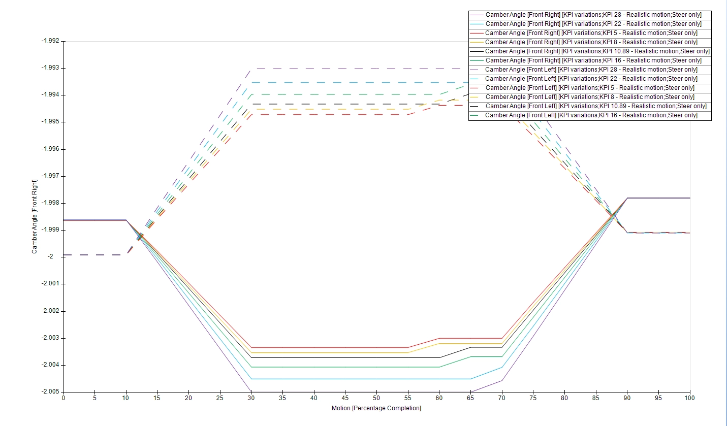
Effect of Kingpin Inclination
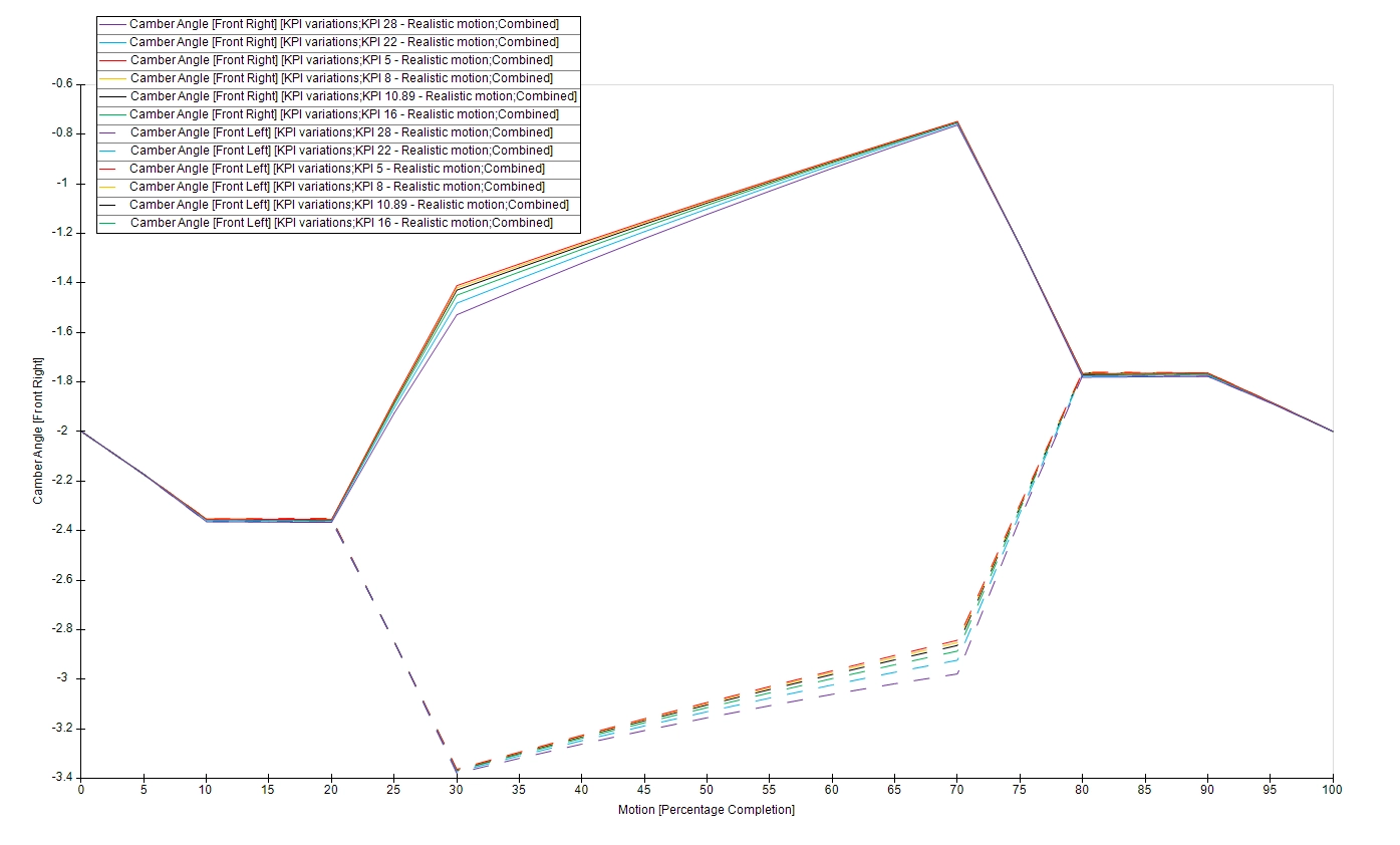
Multiple suspension setups changing the KPI were defined on SOLIDWORKS. As show in the above images. The concluded results on its effect on our suspension showed minimal effect on camber gain during operation.
The range discrete of KPI values simulated varied from 5 to 28 degrees.
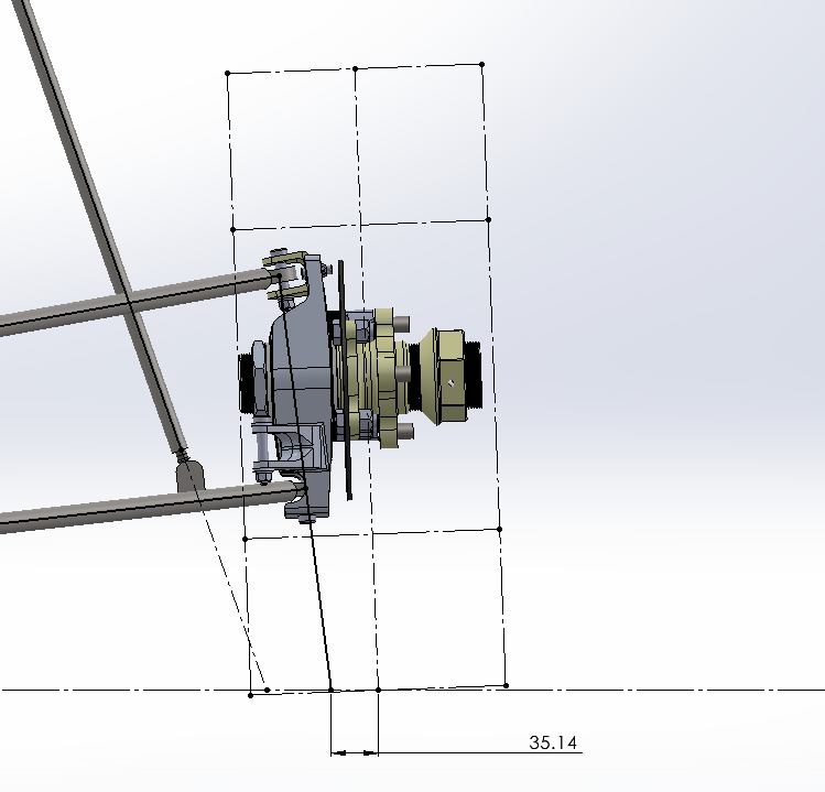
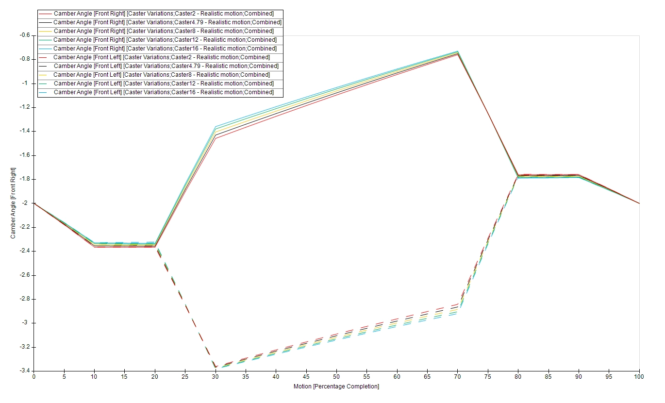
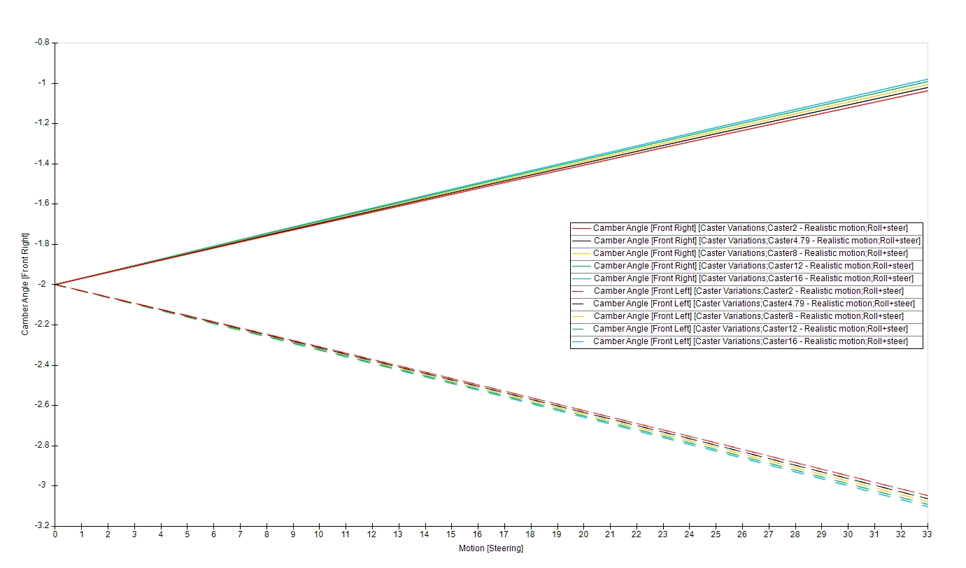
Multiple suspension setups compiled by changing the caster angle were simulated, similar to the analysis on KPI angles, and similarly, minimal effect on camber gain during operation was observed.
The range discrete of Caster angle values simulated varied from 2 to 16 degrees.
When the steering system is modelled, a significant influence is made by the mechanical trail & scrub radius, both of which are heavily influenced by the Caster & KPI. This analysis allows the optimum mechanical trail and scrub radius to be determined, knowing that it won’t negatively affect the kinematics of the suspension system.
The KPI & Caster do practically affect the static steering torque, as excessive values of either causes the tyre to lift during turning…
When changes to the chassis pickup points cannot be made, what properties can be changed to optimize Camber Gain and Chassis roll?
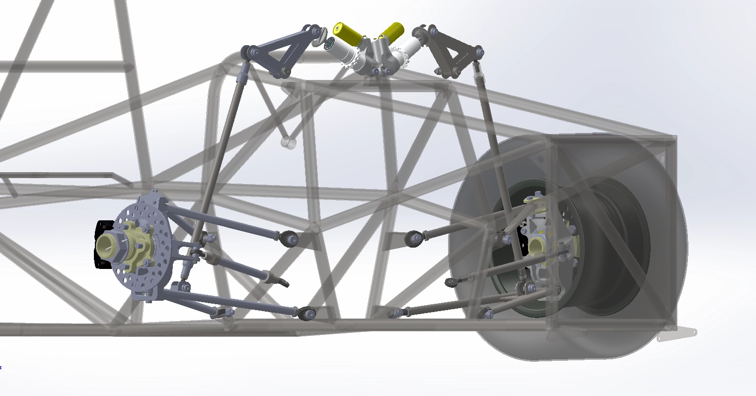
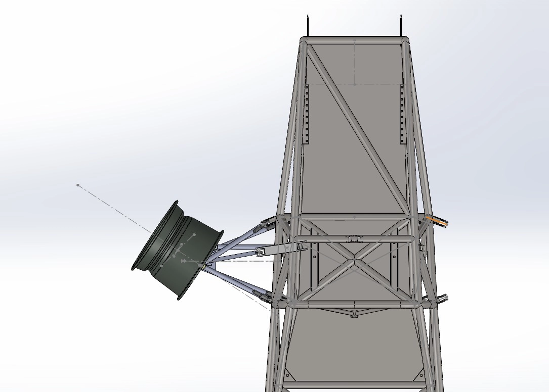
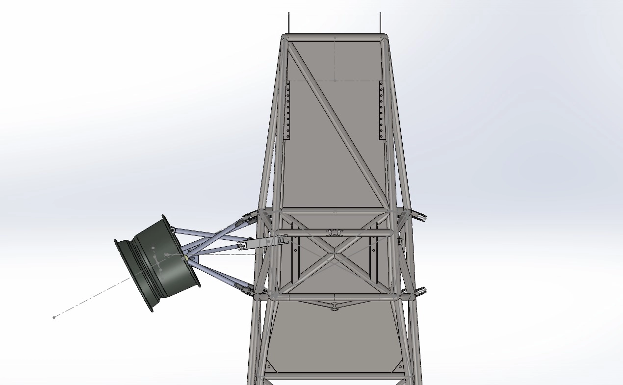
Finalized suspension points for the new upright, avoiding any change to the chassis…
Is the roll center below the ground plane?
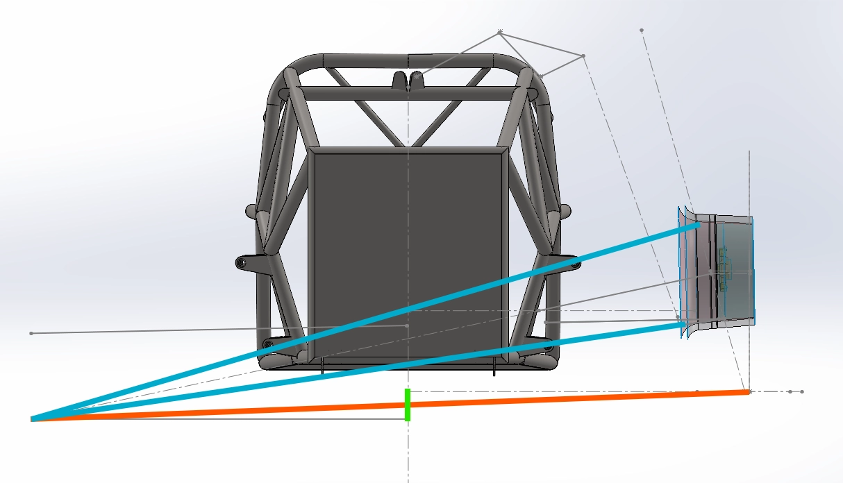
Yes. Highlighted in green, the roll center height was identified as the primary reason for excessive roll due to an abnormally large moment arm. By lowering the lower pickup point on the Upright, we were able to reduce the overall length of the moment arm by 23%.
Minimizing Camber gain during roll…
Camber gain during roll, after multiple iterative simulations, was almost independently dependant on a single geometric property… The Front View Virtual Swing Arm Length (FVVSAL), highlighted in orange – defined by the Instantaneous centre in blue.
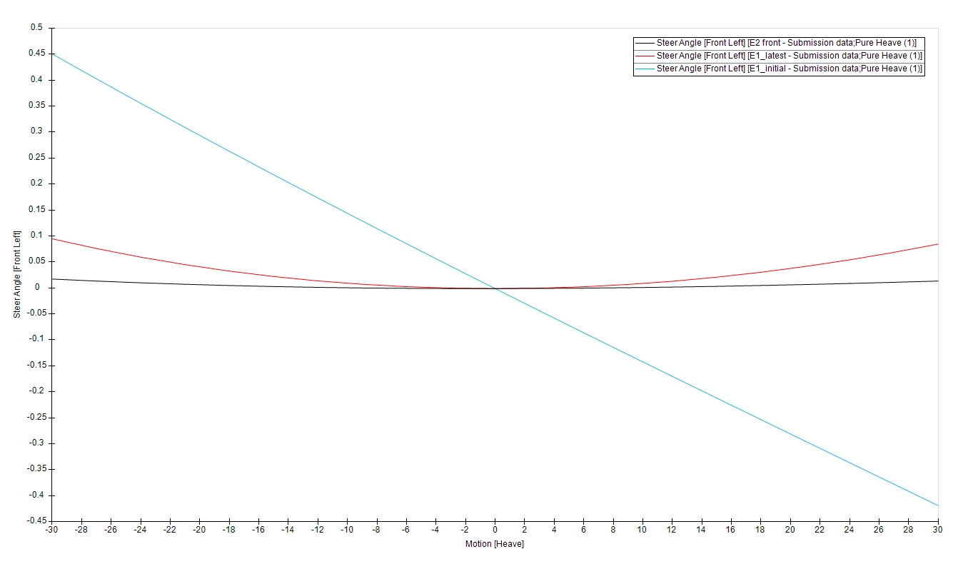
Shown below is the overall improvement of the upgraded suspension system, compared to the initial setup. Also included is the comparison against my design for the E2’s suspension.
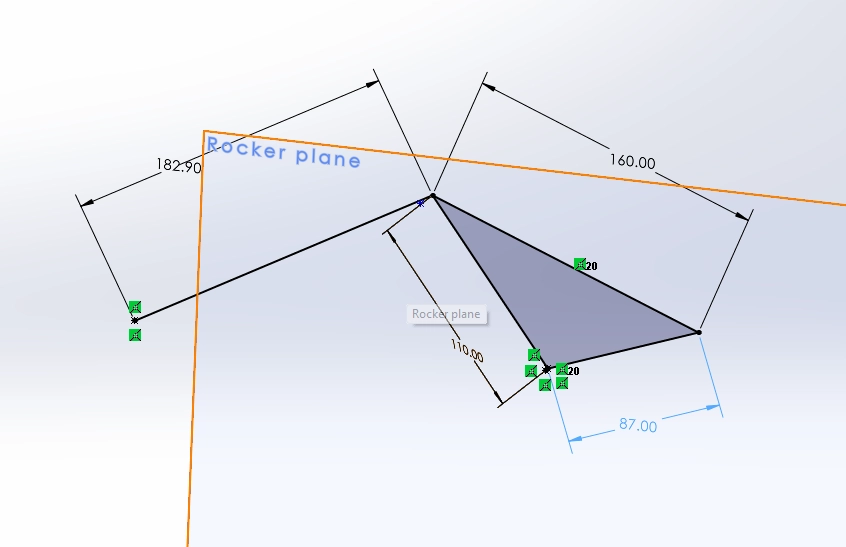
The new upright prompted the design of entirely new suspension links, including the rockers & wishbones.
The rockers’ heave motion ratio was increased from 0.9 to 1.1, effectively further stiffening the suspension.
GD&T was performed as a compromise between maximum tolerance deviation while maintaining acceptable tolerancing for the relevant assembly processes (press fits, bolted assemblies, etc.)
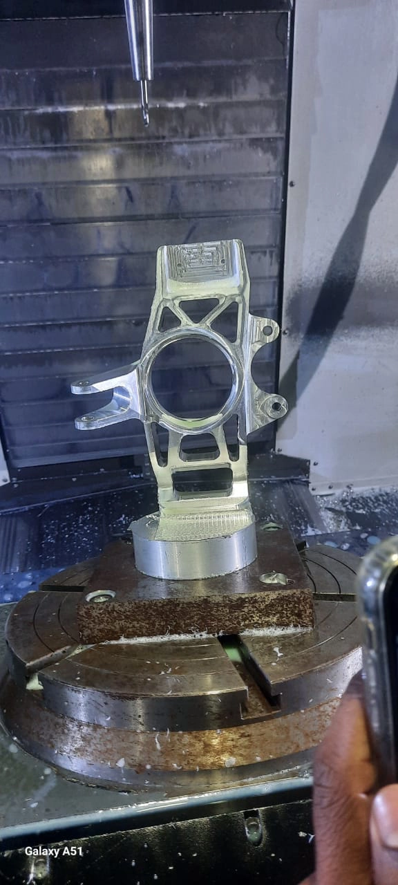
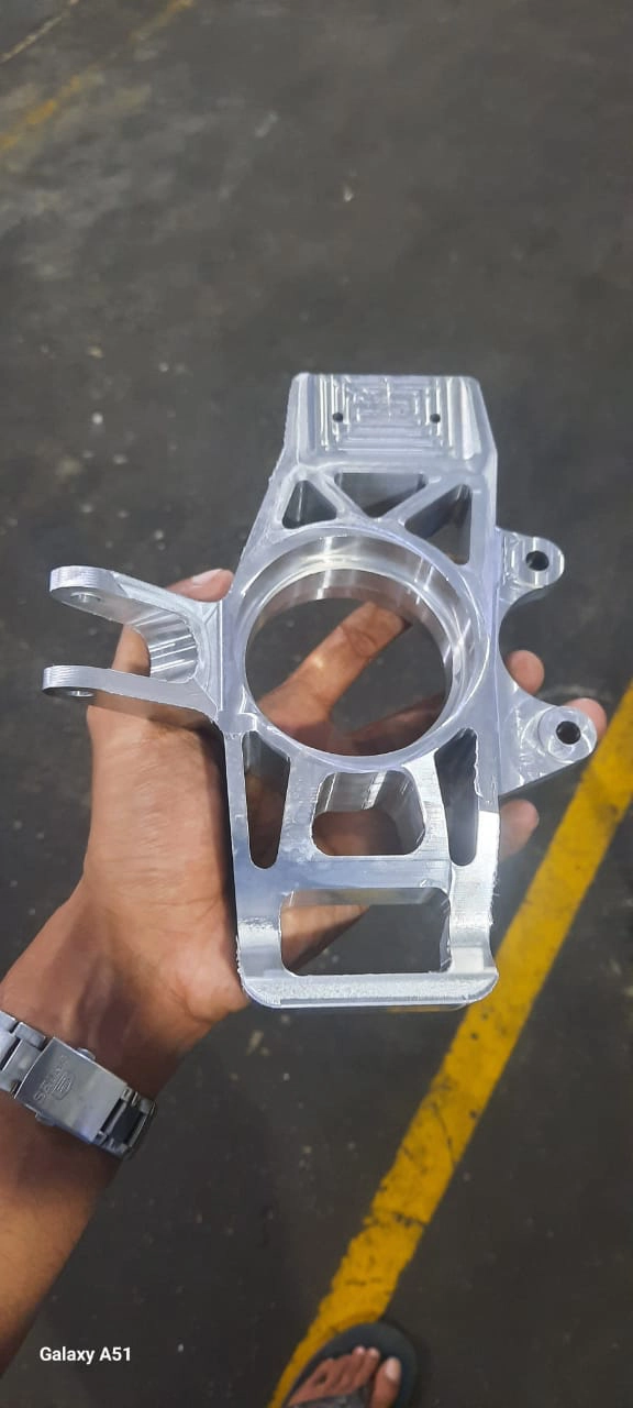
I decided to use 7-inch cylindrical aluminium billets (limited selection due to availability) over 6-inch billets as this woud allow us to achieve a longer steering arm, effectively reducing our steering torque further by a factor of 26%.
Pitch and roll considerably influence the heave motion at the individual wheel. Besides the effect aero, heave is only a consideration in the occasion of a bump. ↩︎
Caster angle can be varied independent to the mechanical trail by offsetting the KP axis from the wheel’s centre ↩︎