All work indicated below are my own and individual contribution.
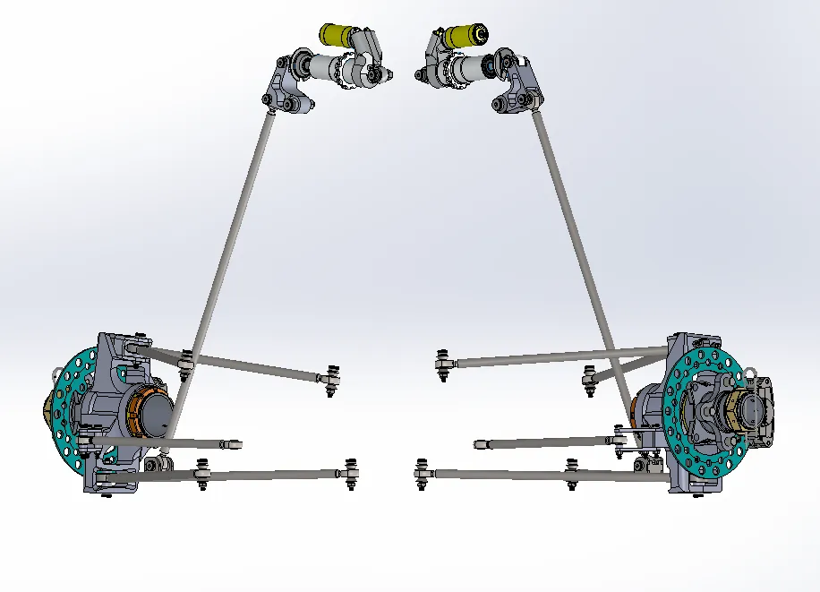
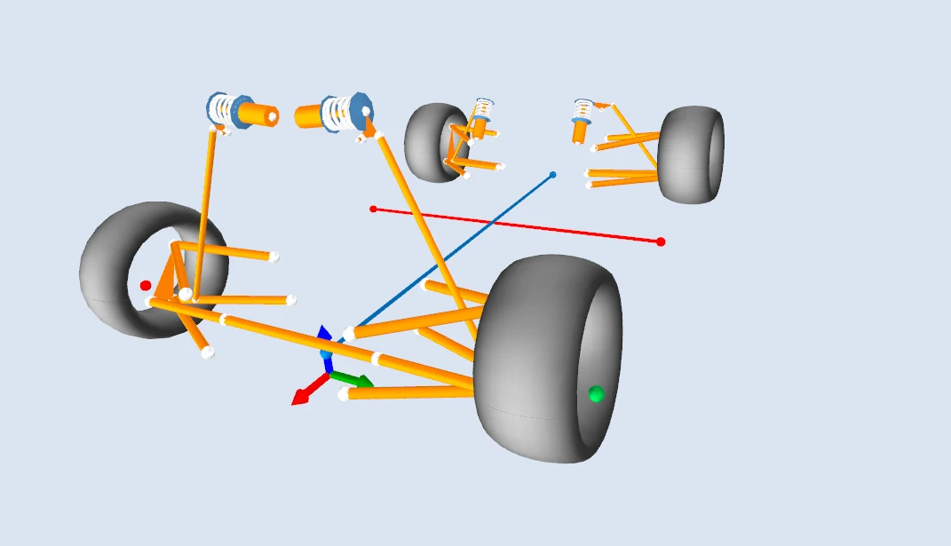
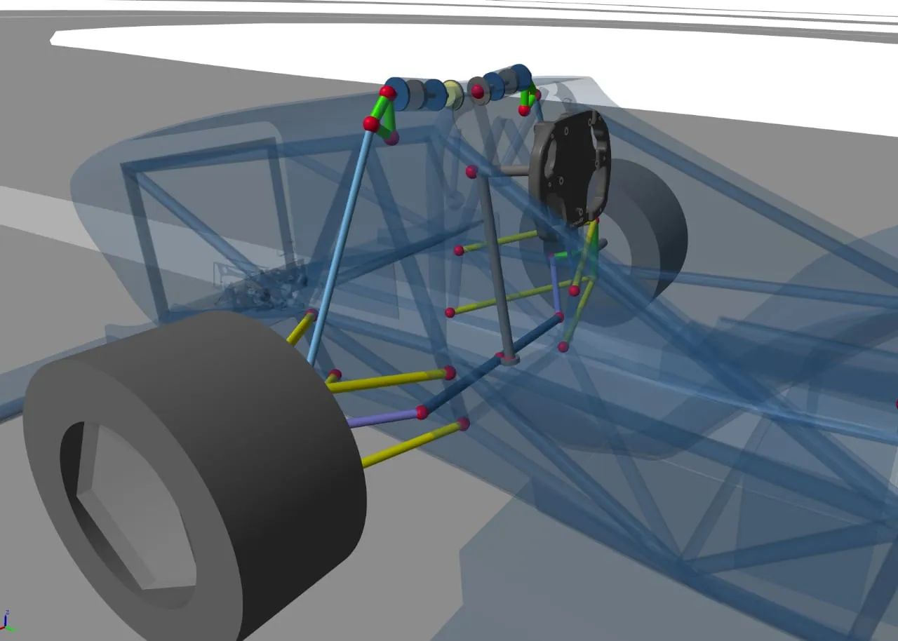
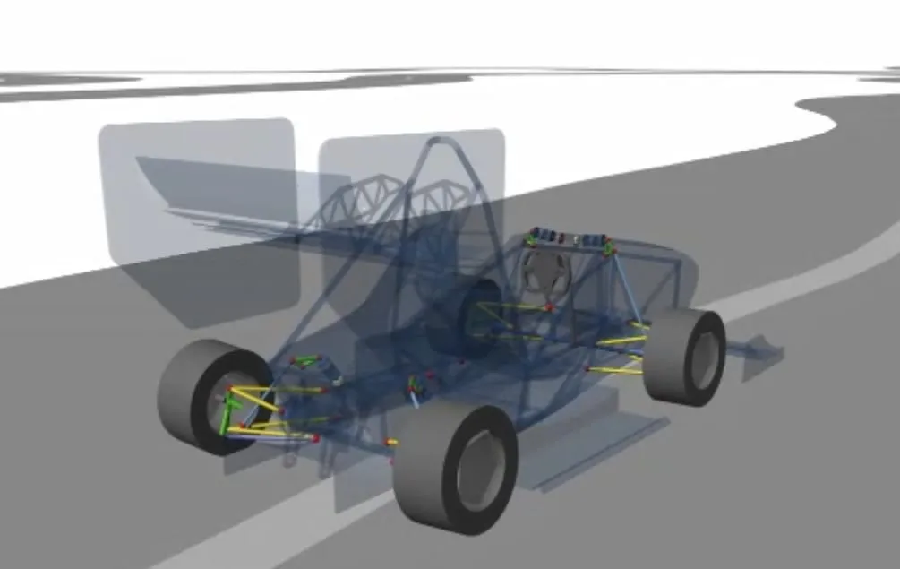
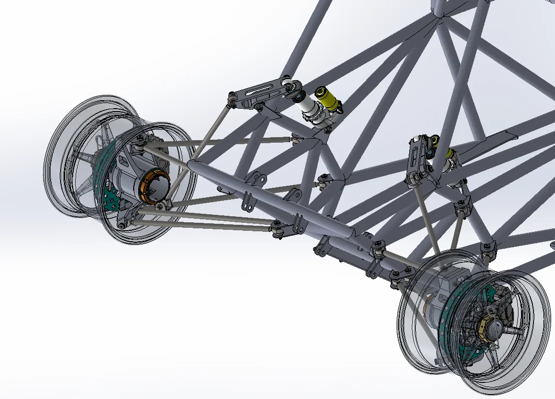
OptimumKinematics simulation of a left-hand corner on the E2. Read more
Performance targets for the E2’s suspension
01
Roll & Pitch Limits
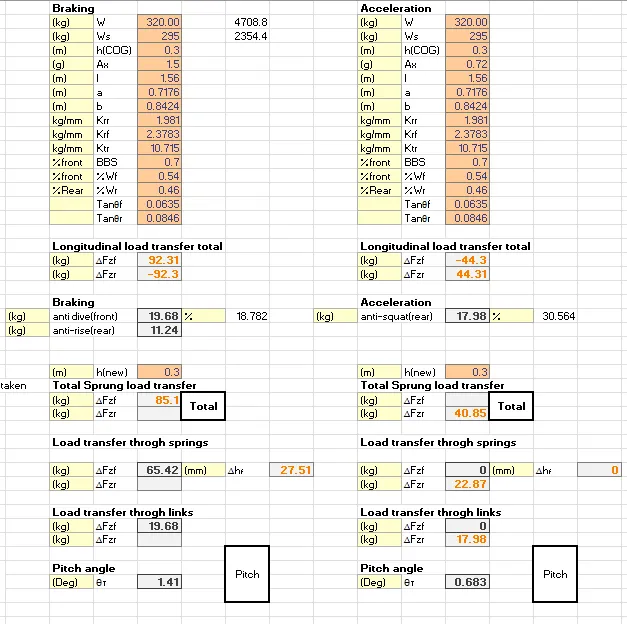
A maximum roll of 1.42 degrees & a maximum pitch of 1.4 degrees in braking & 0.7 degrees in acceleration, each defined by linear roll gradients (per ‘g’)
02
Weight limit
A weight limit of 20kg was imposed on the suspension system with a secondary objective to minimize non-suspended mass.
03
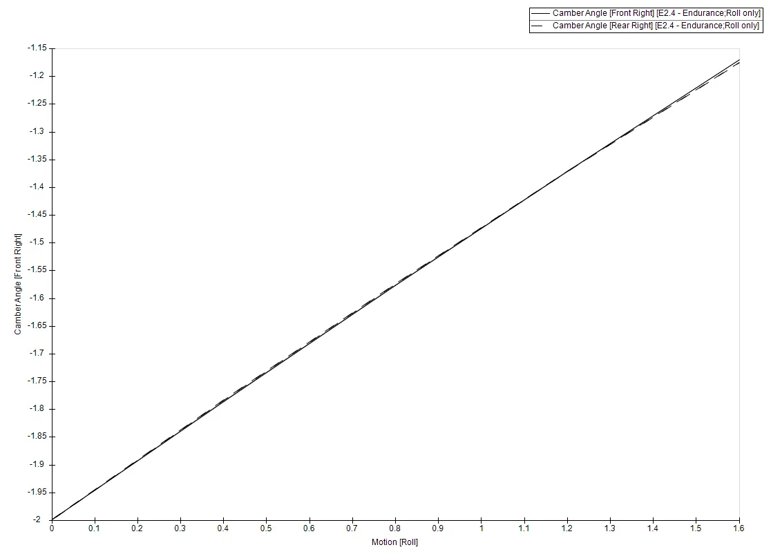
Static camber to be reduced by 55%
Work on the previous car made it clear that the camber gain during operation can be significantly reduced. The new target was set to have static camber of 0.8 degrees.
All the above goals were reached well below the maximum threshold. Read on to see how:)
At a glance
A list of features visibly noticeable on the car’s suspension.
No Anti-Roll Bar
The suspension features no ARB or decoupled system. This negatively impacted the previous car, especially in terms of tunability. My solution: 1. At the expense of tunability, keep the system light. 2. Design the setup to primarily counter roll moments, then utilize anti-features to meet the goals for pitch-stability.
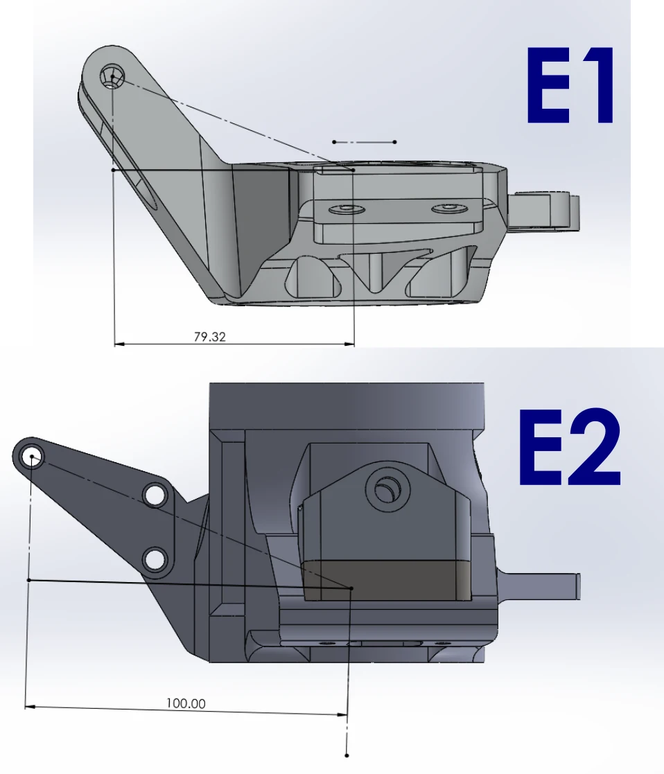
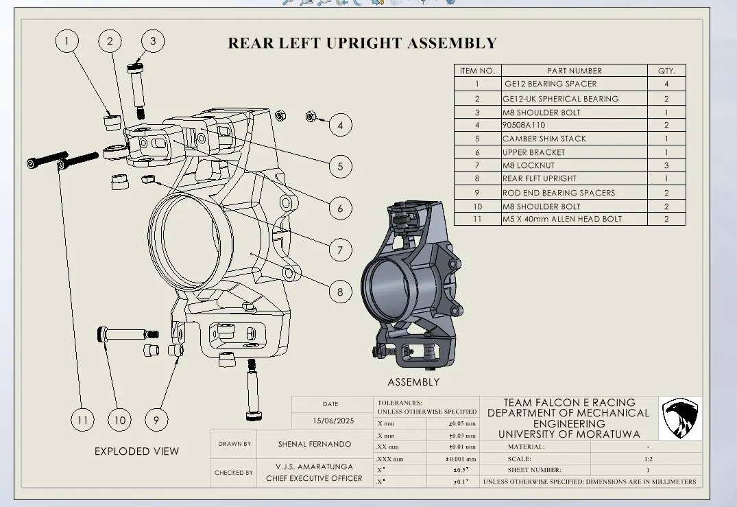
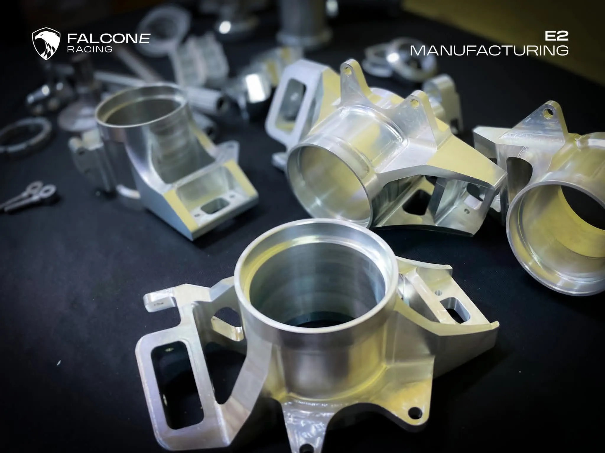
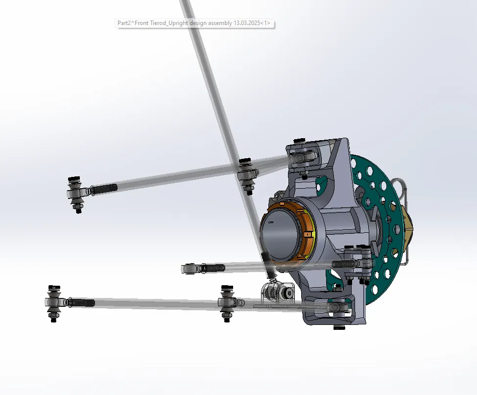
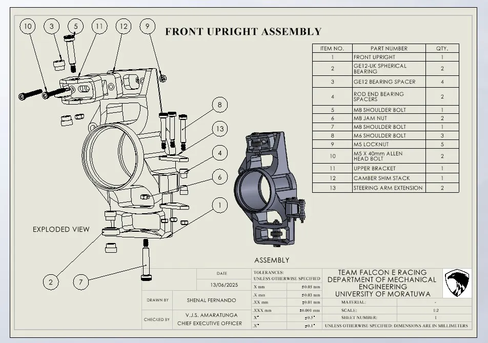
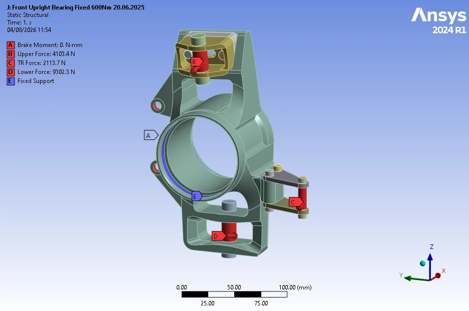
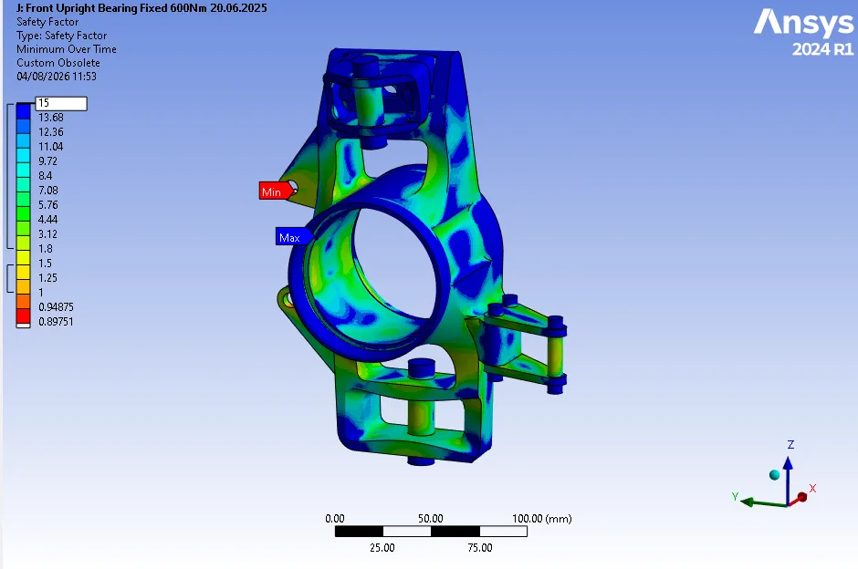
The upright’s design was limited by the availability of larger aluminium billets. This restriction was avoided by simplifying the design into separate components, with the added benefit of adjustability & ease of manufacturing. The moment arm increased from 80mm to 100mm.
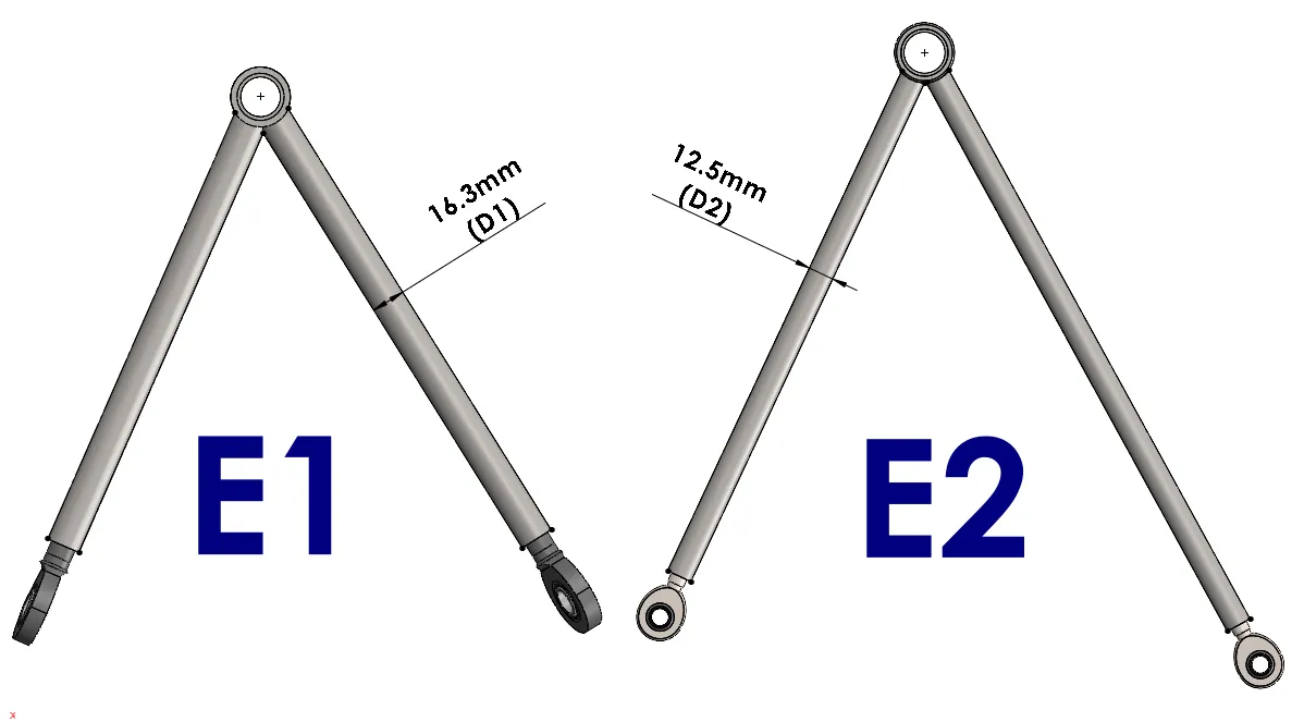
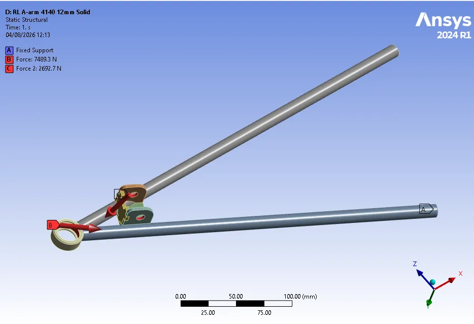
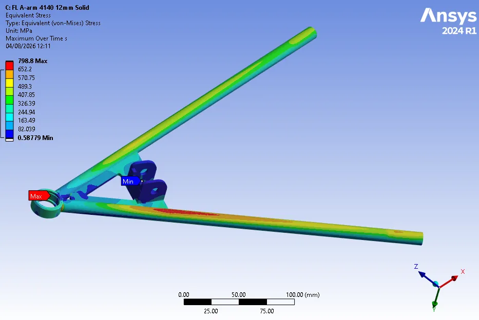
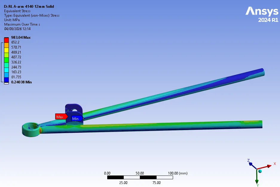
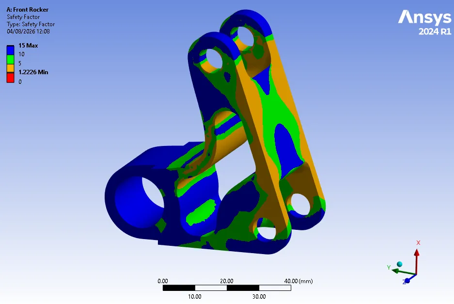
A 23% thinner diameter. This was achieved using a minimum safety factor of 1.2 & by heat treating our A-Arms to increase its yield strength by a factor of 2.7.
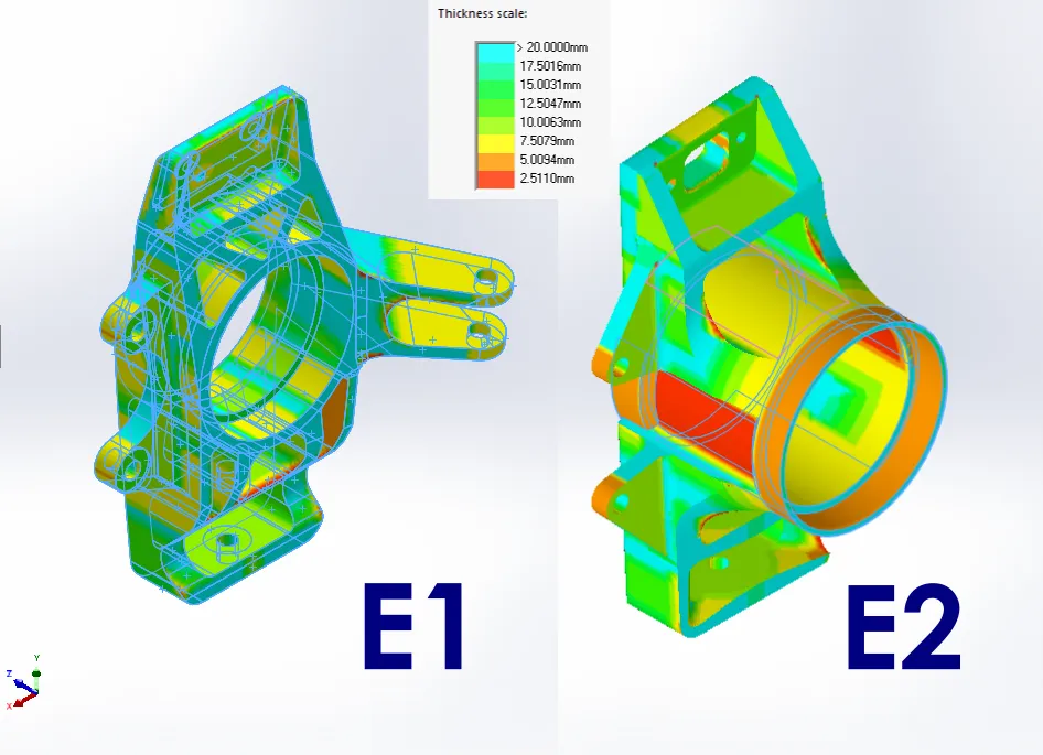
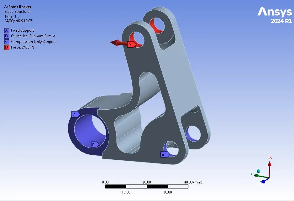
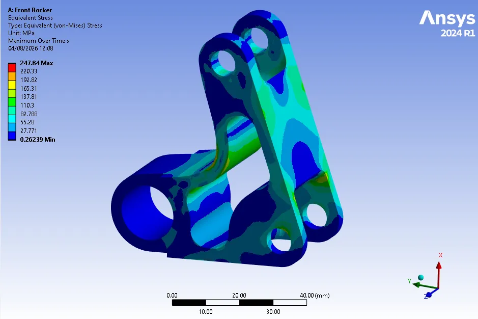
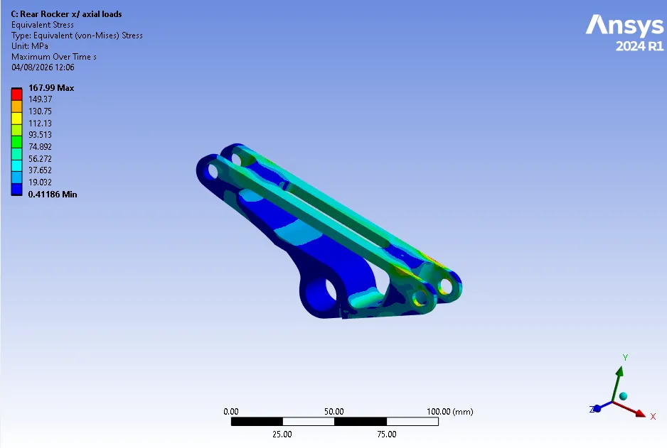
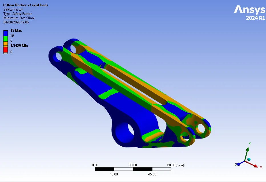
All surfaces orange or darker are between 1.6mm & 5mm in thickness. All machined components were iteratively analysed & optimized (on ANSYS) to produce lightweight components which could be milled on a 3-axis CNC mill.
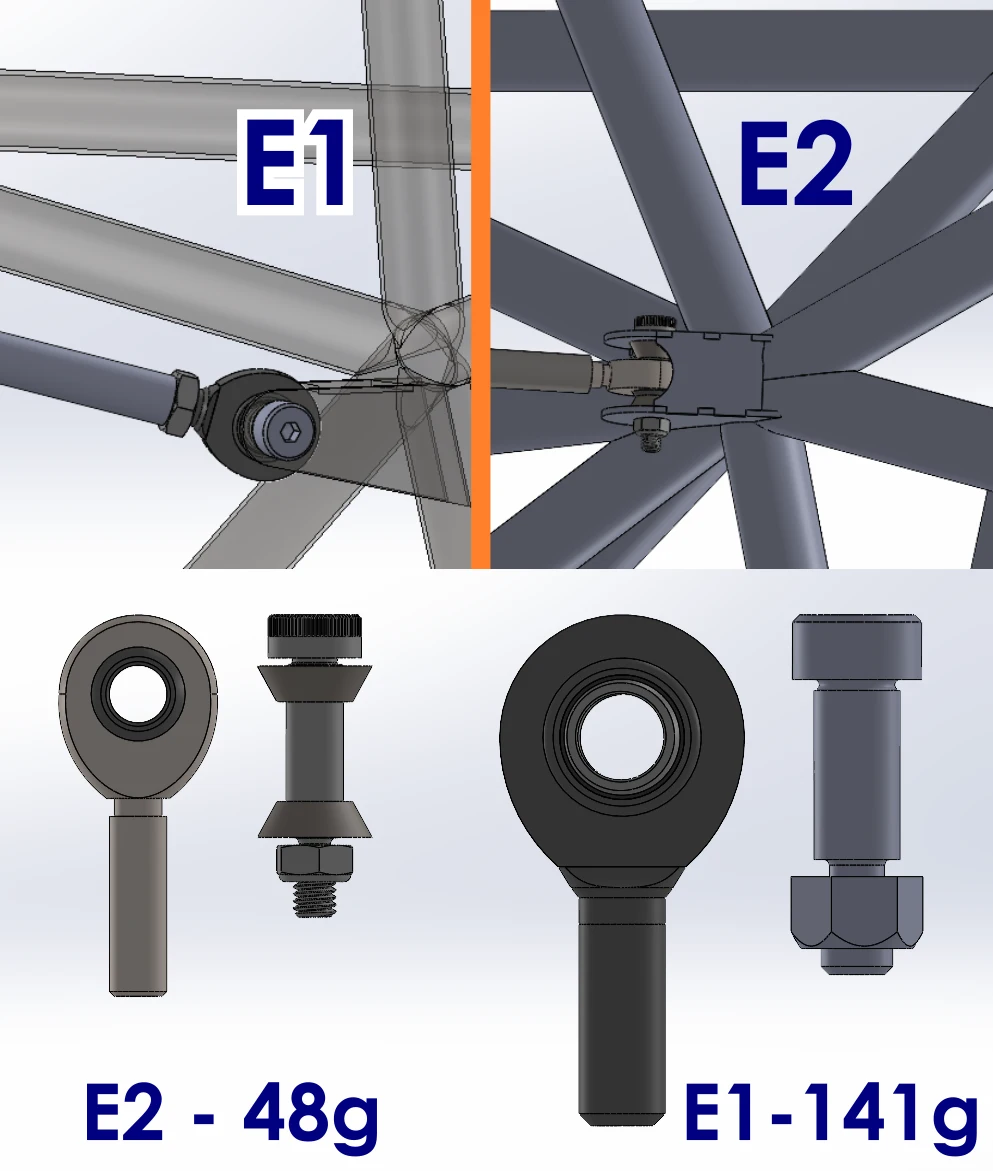
The above changes alone saved 2.9kg of weight on the car. The change in orientation of the rodends axes allowed the major loads to act radially on the bearing, avoiding any large axial loads (as in the E1).
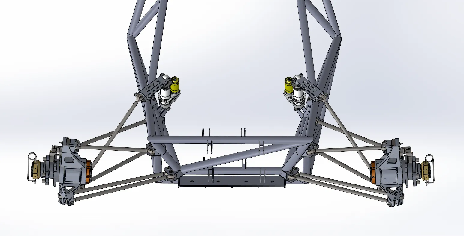
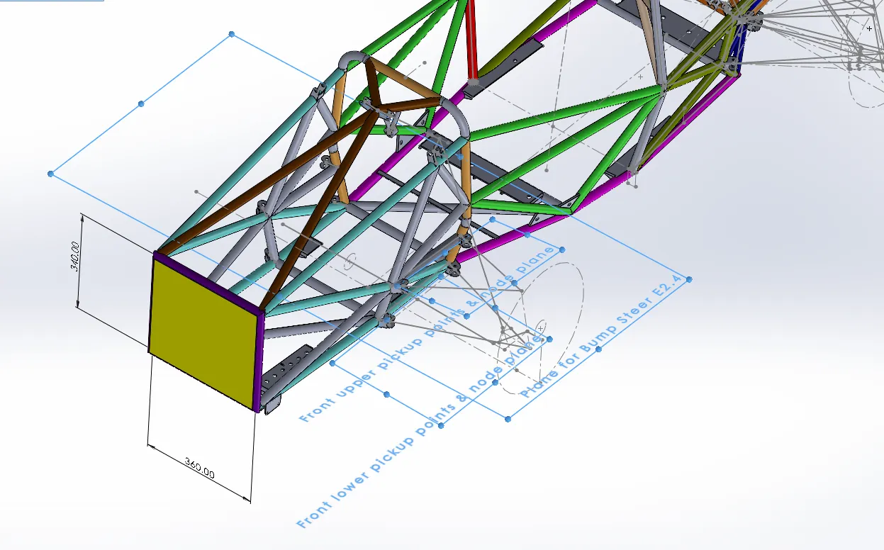
Reducing yaw inertia by increasing the concentration of mass along the car’s centre required the suspension to be located inboard. In the rear, this objective interfered with our wide vertically oriented drivetrain. This was overcome by a unique actuation layout. Radial clearances within the wheel & critical attachment points were just above 5mm (limited by FS rules). The entire rear chassis was parameterized by the suspension geometry, such that even the drivetrain’s angle of inclination & translation was determined by the roll centres & anti-geometry.
The E1 car gave me the opportunity to learn the fundamentals and troubleshoot existing FS suspension systems. It allowed me to optimize and produce a functional suspension system with a constrained chassis & wheel hub (Read more on the E1)
It was the E2 – our 2nd car- that my team and I initiated that provided the opportunity to design an entirely new suspension system constrained only by predetermined performance targets.
System showcase
The Rocker Assembly
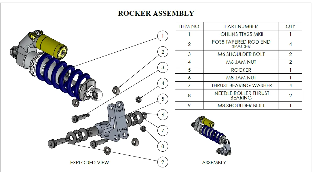
The rocker assembly’s component count increased from 8 on the E1 to 17 on the E2. This was largely due to the reworked spacer designs & the new bearing assembly featuring, a needle bearing, 2 thrust bearings & 4 thrust washers. The assembly was still 112g lighter than the previous design & devoid of the “sticky” behaviour due to binding at the pivot from the previous design. The design was so effective & compact, that a similar bearing assembly was later implemented on the steering column as well.
More in depth
An extremely brief list of a select-few design features & considerations incorporated in the design.
Kinematic Design
A thorough understanding of the influence of various geometric parameters of a double wishbone suspension system, including troubleshooting & cause-and-effect analysis was established a I redesigned the E1’s suspension (Read more)
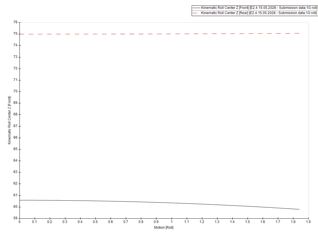
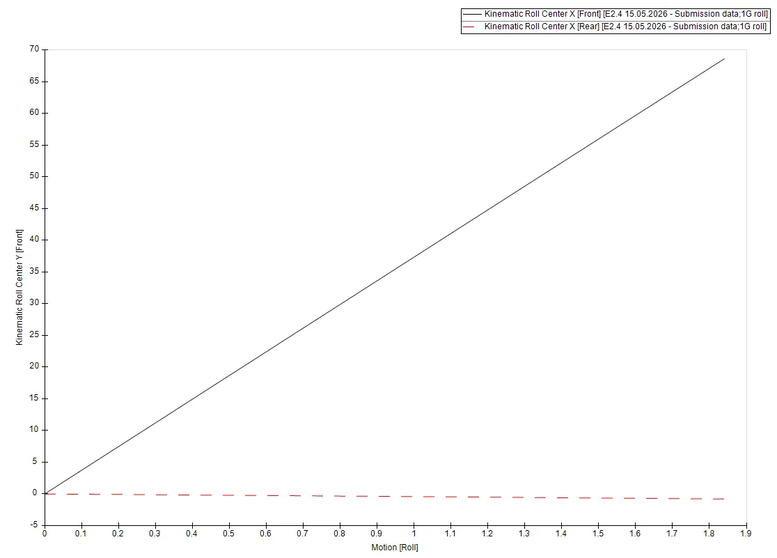
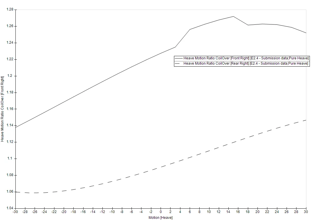
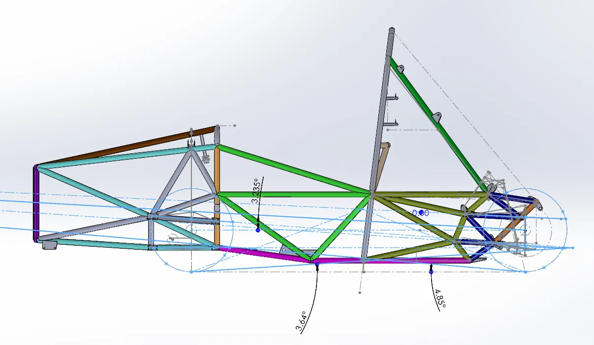
The graphs below show the improved kinematic behaviour of the E2 achieved by maximizing the available space within the wheel, implementing a shorter swing arm in both side view & front view, higher roll & pitch centers, & a lot more intentional design features. See the 3D simulation performed OptimumKinematics above.
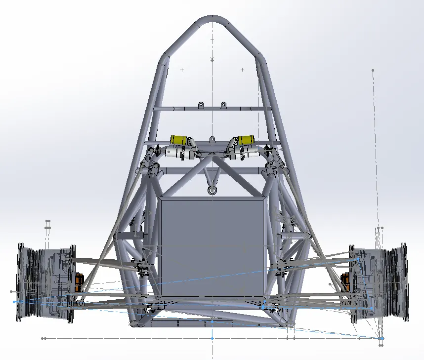
Left &Right front wheel instantaneous centres in red & green respectively. Pitch axis in red. Roll axis in blue.
The design showed high stability & linearity throughout its range of motion.
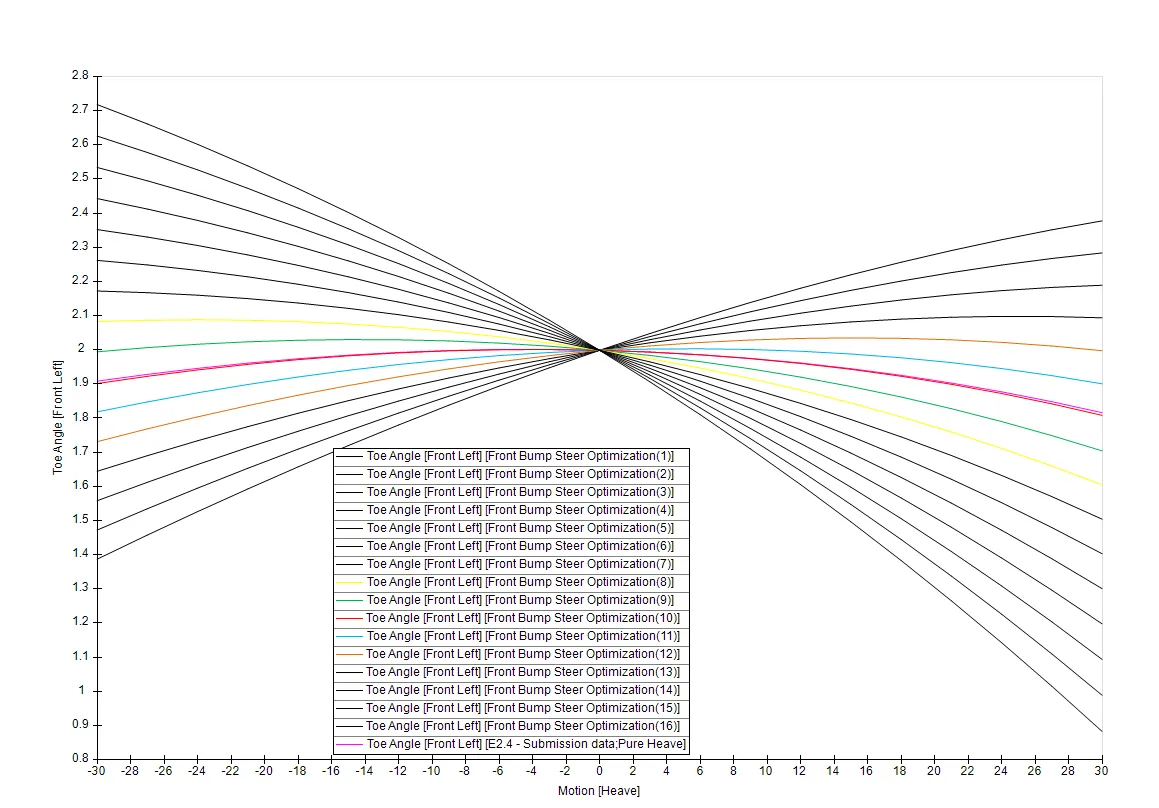
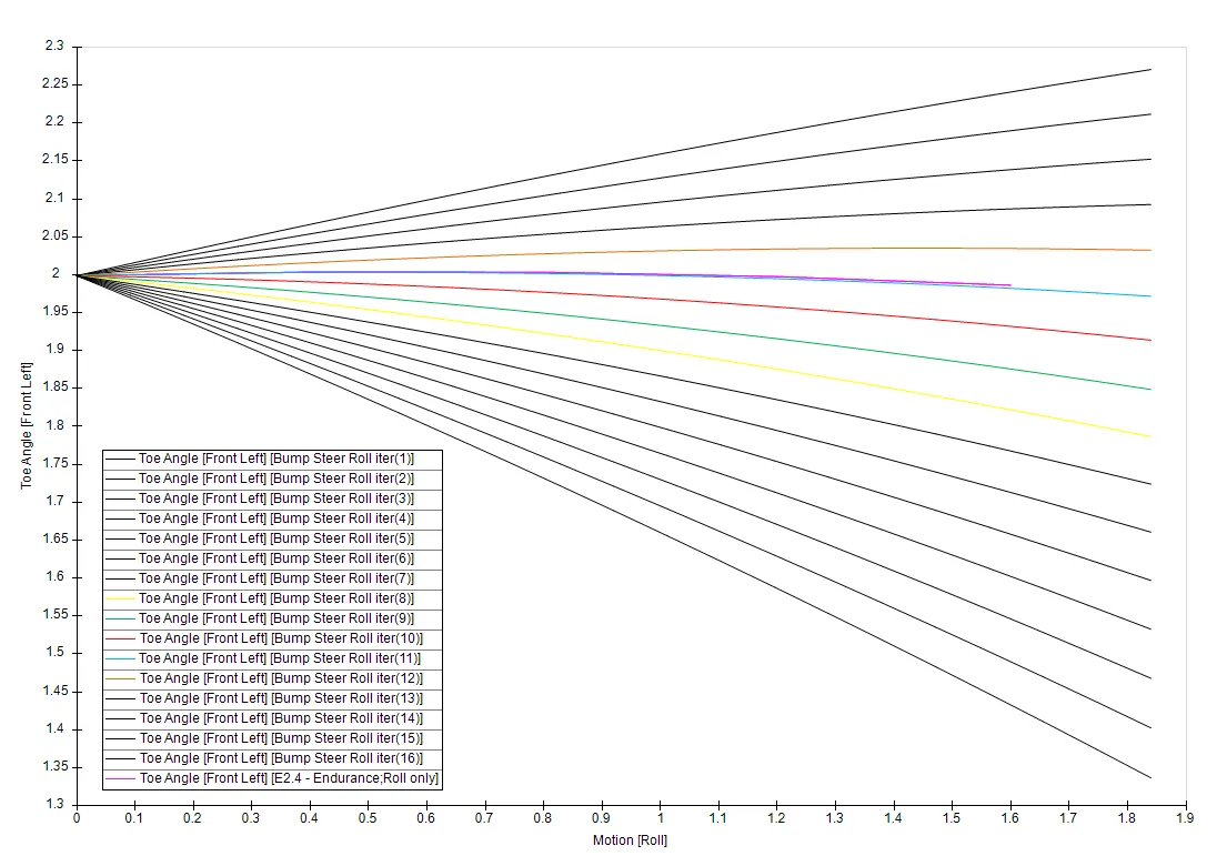
The most interesting aspect of the kinematic optimization I experienced was the optimization of bump steer characteristics in the presence of Anti-squat, Anti-dive and Anti-lift geometry. The problem evolved from a 2D problem in front view to a 3D analysis of planes with intersecting axes non-parallel to the car’s centreline. Although non-linear, bump steer was minimized drastically throughout the entire motion (see graphs below).
Although our Vehicle Dynamics team was developing a full car model (credit due to our splendid VD team of 2024/25) on Simulink, it lacked validation, so all results derived from the model were used skeptically.
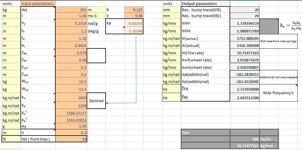
In order to overcome this uncertainty, I resorted to first-principle design & calculations based off textbooks such as Milliken’s, simplified the loads on a quarter-car model & resolved the forces using matrices.
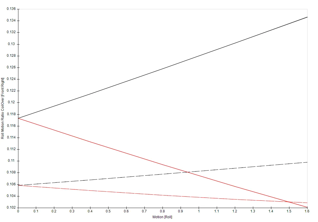
The heave motion ratios, roll motion ratios, roll centre heights & anti-percentages were finalized parallelly to achieve the desired dynamic behaviour of the car. Rising rates were implemented on the rocker’s design.
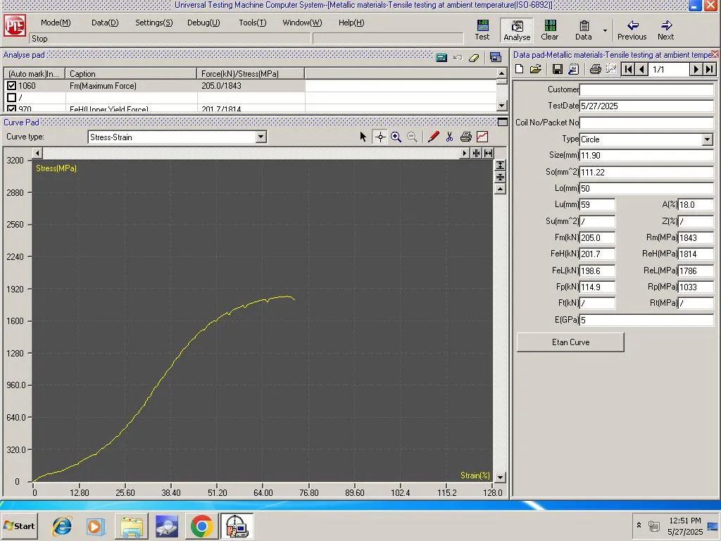
The heat treatment I performed provided the alloy we used on our A-arms with a yield strength exceeding 1500MPa, which was significantly higher than the 1280MPa used for the design procedure (See the Stress Curve – And Yes, we do still use WindowsXP). After using 4 samples to analyze consistency, we were unable to obtain the UTS as we were advised laboratory was not equipped to apply more tensile load on the sample.
Although presented in the latter stages of my article, it should be noted that kinematic design & component design occurred parallel so that interference or spatial restrictions may be accounted for in the final kinematic layout..
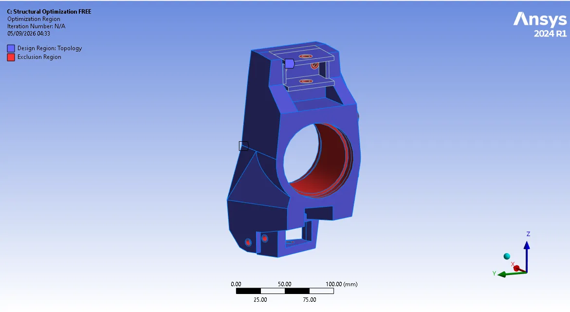
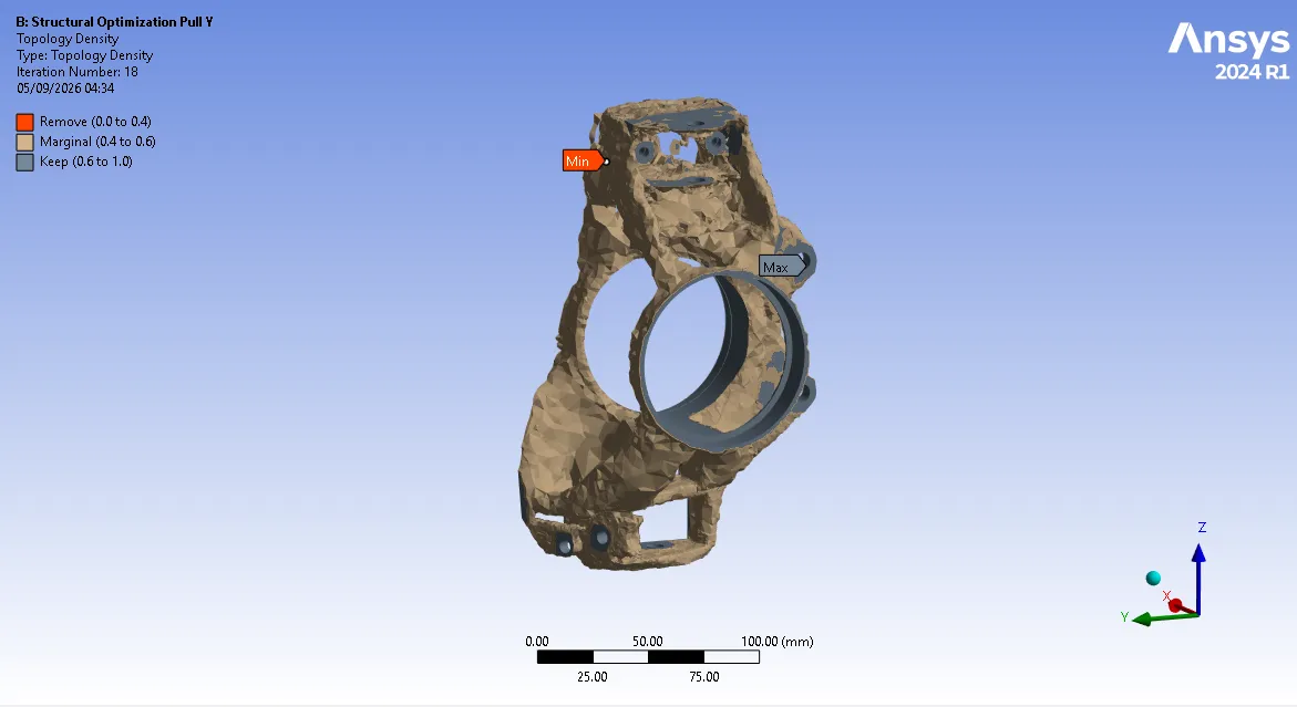
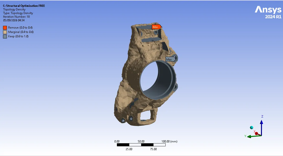
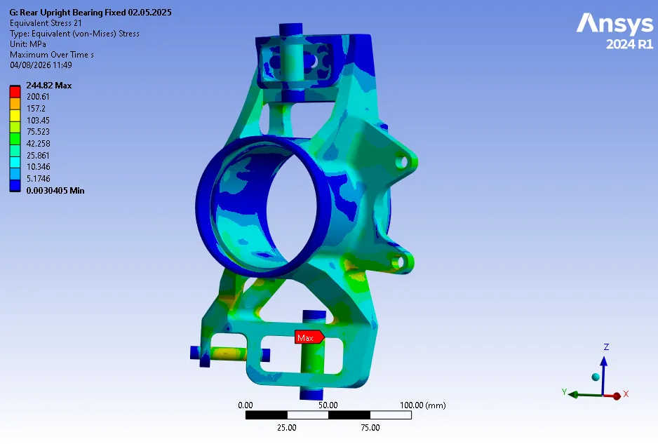
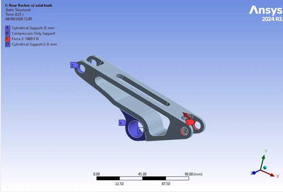
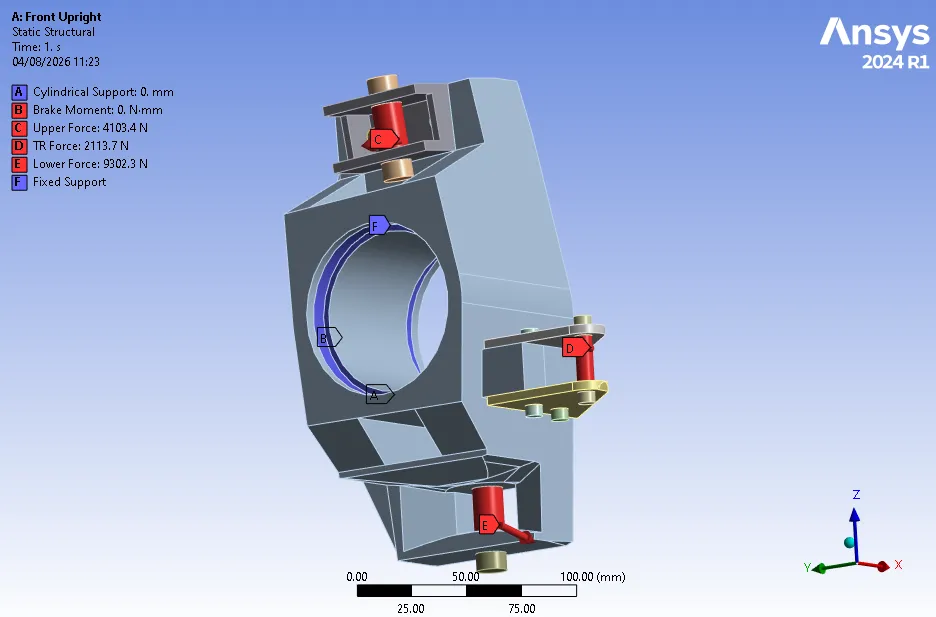
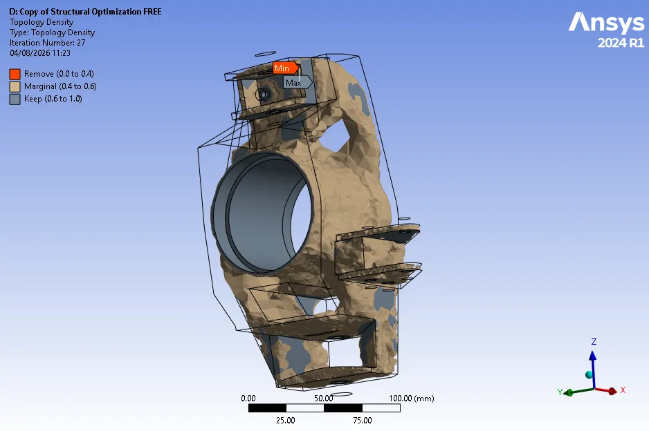
Components were structurally optimized individually on ANSYS, with the available workspace & workpiece size used as spatial limits, & subjecting each component to it’s combined maximum loading cases along each kinematic points’ component directions.
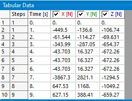
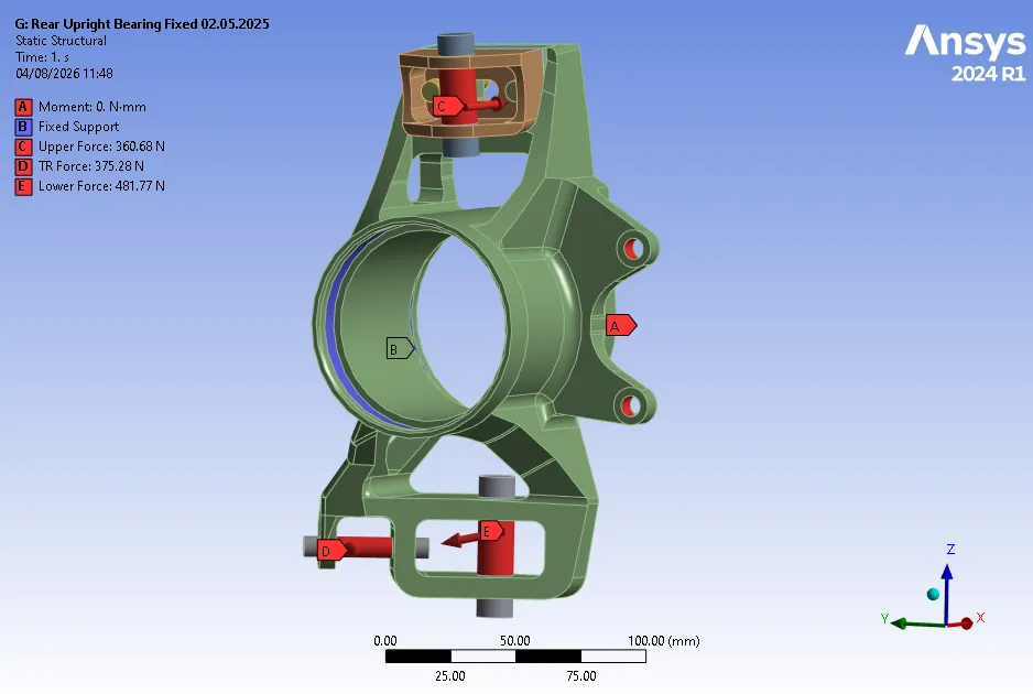
For example, the rear upright below was subjected to 16 unique loading scenarios, processed in a single optimization to produce the final CNC capable design.