
All work indicated below are my own and individual contribution.
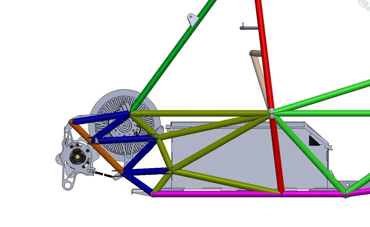
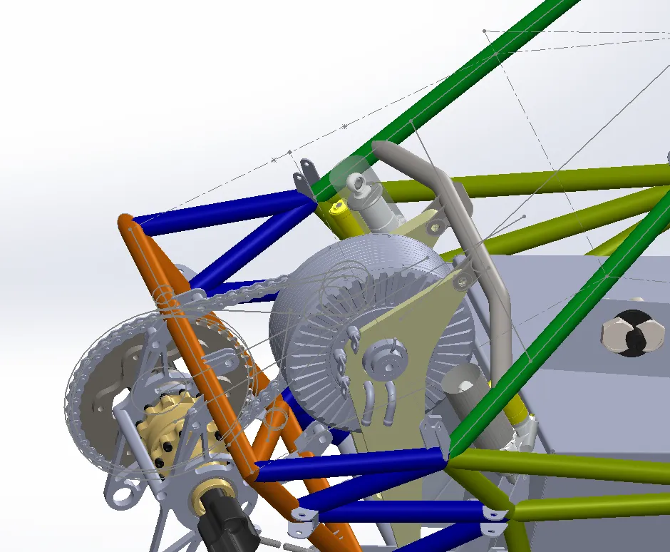
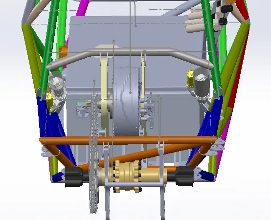
On the left, the old motor mounting assembly, and the new one on the right
The above change would seem minor, but it was the largest change made to the chassis in the 2026 season, owing to the rule change disallowing the attachment of the motor to the rear impact structure.
The challenge in this particular design was the time and cost constraints, where a feasible design had to be done, preserving the existing chassis & the remaining powertrain components.
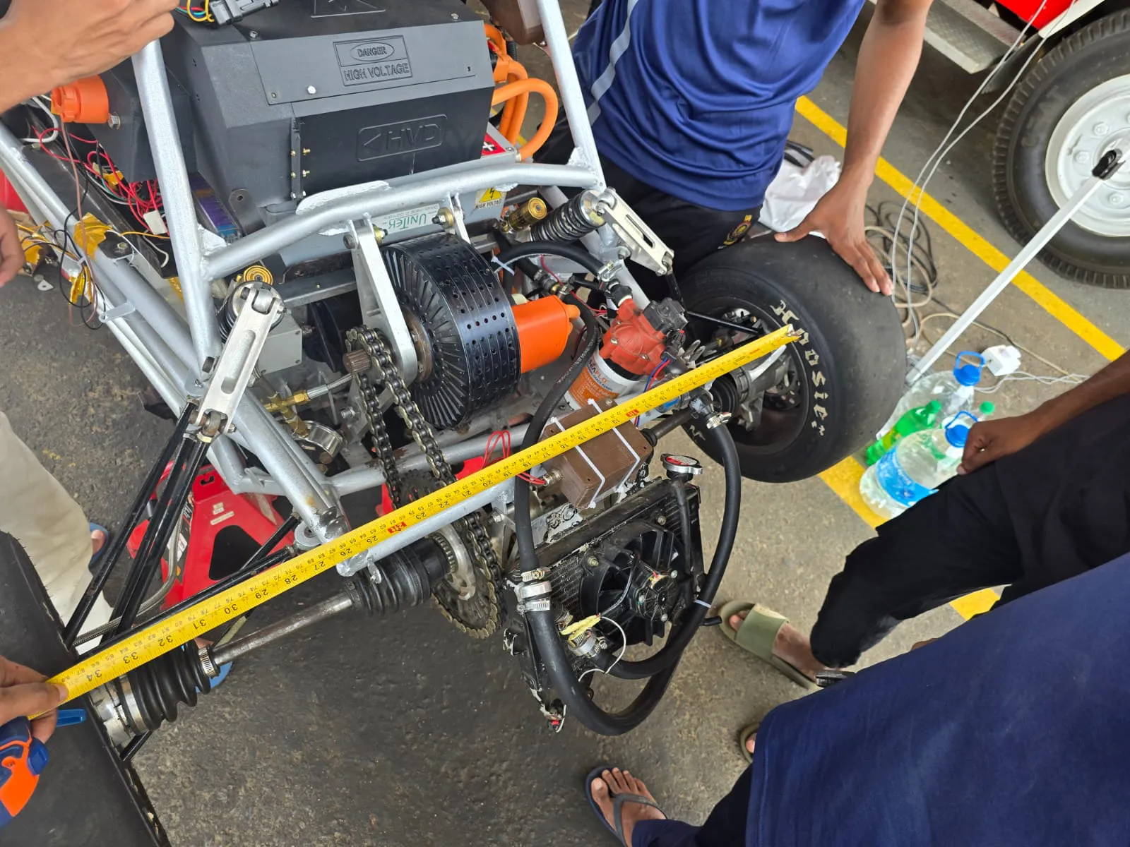
All the while, the clearance between the chain & the chassis was less than 10mm.
Analysis & Design
Modelling the system
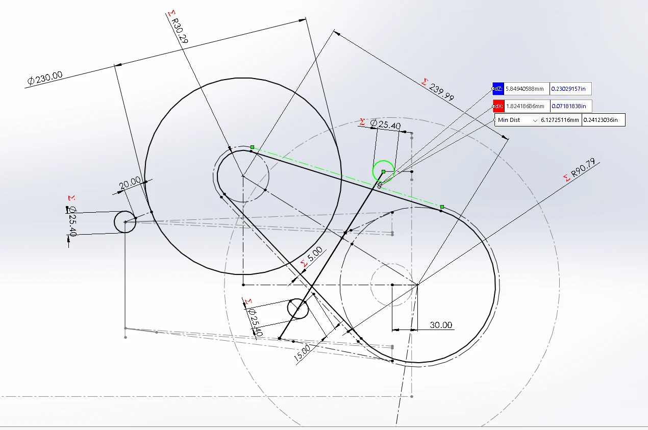
The orientation & center-to-center distances of the differential & motor were obtained by constraints applied on a parameterized chassis CAD (SOLIDWORKS). Read more on the E2’s suspension & chassis design.
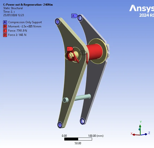
The multibody FEA depicted above was performed to further cement the validity of the reaction forces we obtained using analytical methods. The correlation was positive as the reaction forces from the FEA analysis was within 5% of the calculated forces.
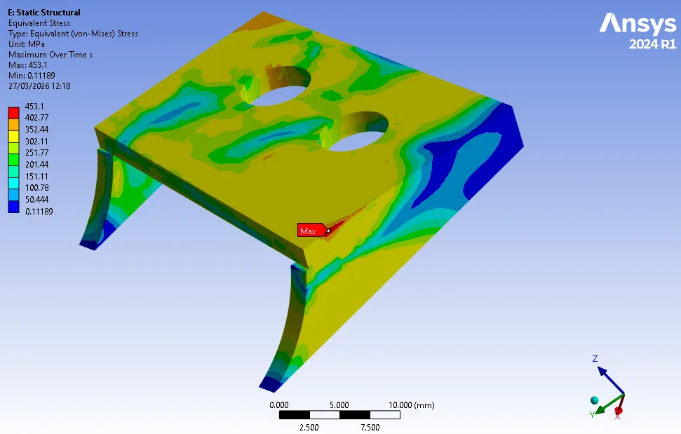
Once the forces were reliably determined, component-wise structural optimization began. Shown below is the stress analysis on the finalized motor mounting bracket.
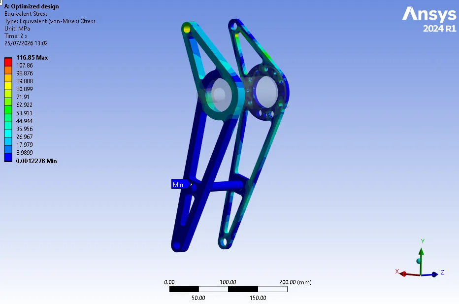
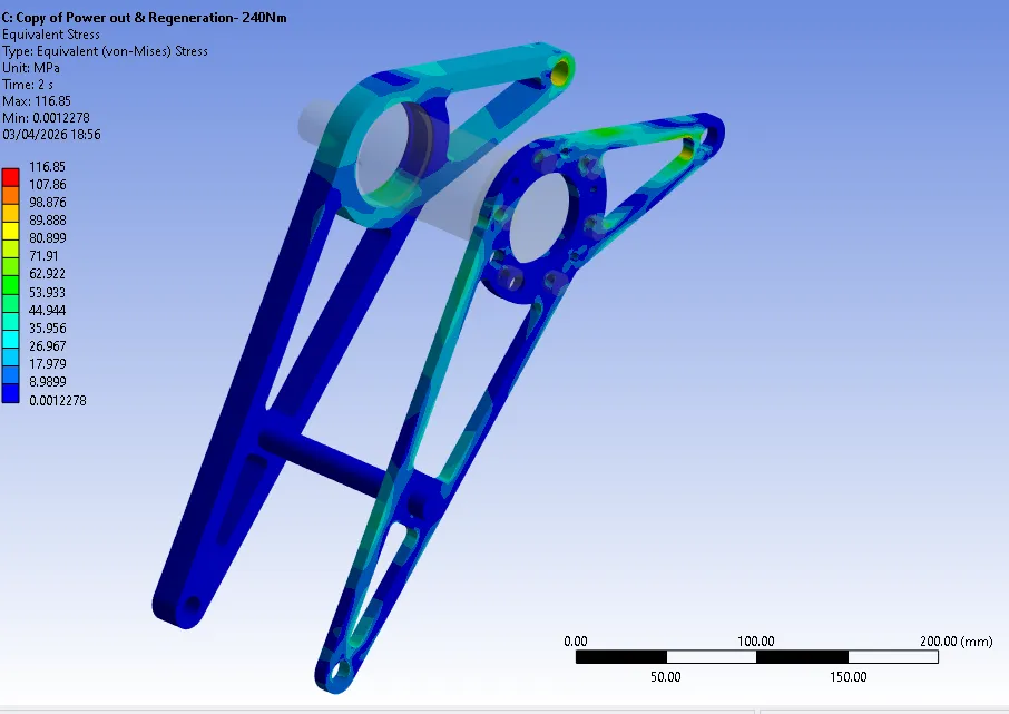
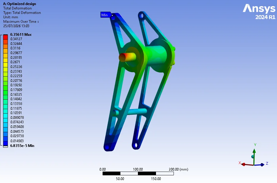
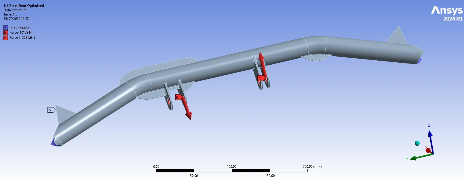
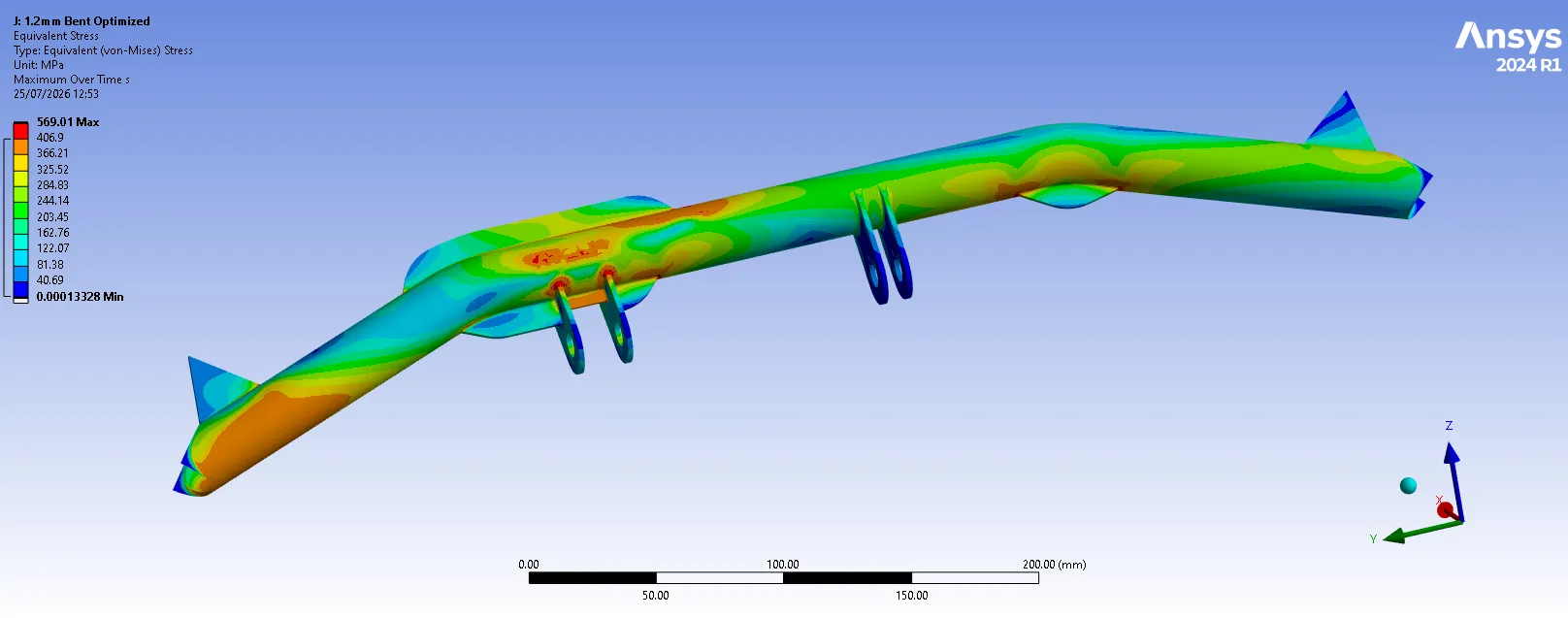
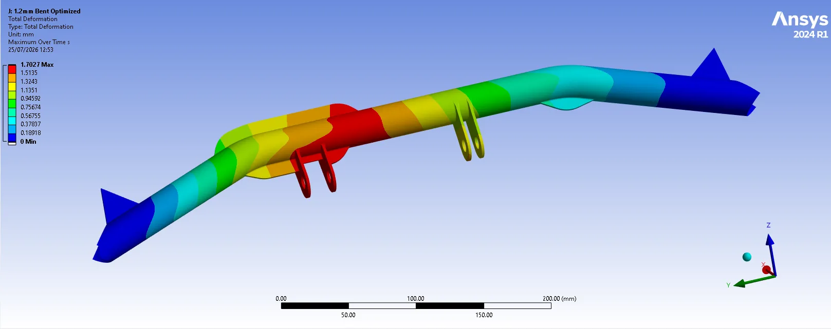
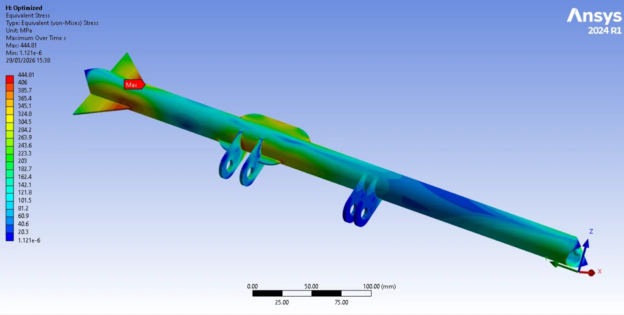
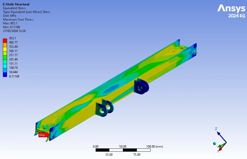
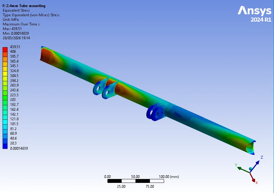
In order to obtain the optimal solution for the chassis tube which will hold the upper mounting points of the shown motor brackets, I conducted multiple design studies, analyzing the structures’ behaviour under varying force vectors.
Finalized Design
The above design were particularly heavy & I believed we could obtain a better solution. Analyzing commercial car chassis, I was inspired to proceed with a design reinforced with ‘bend’s. The final design was only half the thickness of the previous tubular design.
The analysis shown below simulates shock loading which could occur in the case of an error from the electrical powertrain. The analysis showed although the material would yield, the damage would not be “catastrophic”.